Passive Components Blog
No Result
View All Result
  • Home
  • NewsFilter
    • All
    • Aerospace & Defence
    • Antenna
    • Applications
    • Automotive
    • Capacitors
    • Circuit Protection Devices
    • electro-mechanical news
    • Filters
    • Fuses
    • Inductors
    • Industrial
    • Integrated Passives
    • inter-connect news
    • Market & Supply Chain
    • Market Insights
    • Medical
    • Modelling and Simulation
    • New Materials & Supply
    • New Technologies
    • Non-linear Passives
    • Oscillators
    • Passive Sensors News
    • Resistors
    • RF & Microwave
    • Telecommunication
    • Weekly Digest
    Credit: Institute of Science Tokyo

    Researchers Demonstrated 30nm Ferroelectric Capacitor for Compact Memory

    Towards Green and Sustainable Supercapacitors

    Mechano-Chemical Model of Sintered Tantalum Capacitor Pellets

    Bourns BTJ Thermal Jumper Chips for PCB Heat Management

    One‑Pulse Characterization of Nonlinear Power Inductors

    Wk 51 Electronics Supply Chain Digest

    Samsung Unveils World First CLLC Resonant 1kV 33nF C0G MLCC in 1210 Size

    Bourns Releases 500VDC 690VAC Fuse to Protect Power Semiconductors

    Samsung MLCC Replacing Aluminum Polymer Capacitors in AI Systems

    Trending Tags

    • Ripple Current
    • RF
    • Leakage Current
    • Tantalum vs Ceramic
    • Snubber
    • Low ESR
    • Feedthrough
    • Derating
    • Dielectric Constant
    • New Products
    • Market Reports
  • VideoFilter
    • All
    • Antenna videos
    • Capacitor videos
    • Circuit Protection Video
    • Filter videos
    • Fuse videos
    • Inductor videos
    • Inter-Connect Video
    • Non-linear passives videos
    • Oscillator videos
    • Passive sensors videos
    • Resistor videos

    One‑Pulse Characterization of Nonlinear Power Inductors

    Thermistor Linearization Challenges

    Coaxial Connectors and How to Connect with PCB

    PCB Manufacturing, Test Methods, Quality and Reliability

    Transformer Behavior – Current Transfer and Hidden Feedback

    Choosing the Right Capacitor: The Importance of Accurate Measurements

    RF Inductors: Selection and Design Challenges for High-Frequency Circuits

    Transformer Safety IEC 61558 Standard

    3-Phase EMI Filter Design, Simulation, Calculation and Test

    Trending Tags

    • Capacitors explained
    • Inductors explained
    • Resistors explained
    • Filters explained
    • Application Video Guidelines
    • EMC
    • New Products
    • Ripple Current
    • Simulation
    • Tantalum vs Ceramic
  • Knowledge Blog
  • Suppliers
    • Who is Who
  • PCNS
    • PCNS 2025
    • PCNS 2023
    • PCNS 2021
    • PCNS 2019
    • PCNS 2017
  • Events
No Result
View All Result
Passive Components Blog
No Result
View All Result

USB 3.0 Connectors – Architecture, Protocol and Power Management

14.9.2021
Reading Time: 3 mins read
A A

Architecture: from High-Speed to Super-Speed
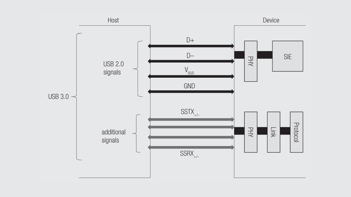
USB 3.0 consists of a physical super-speed bus in addition to the physical USB 2.0 bus (as illustrated by Figure 2.119). The protocol defines a dual simplex signalling mechanism with a rate of 5 Gbits/s. This enables the simultaneous transfer of data to and from the device, as opposed to the single duplex unidirectional USB 2.0 bus.

Fig. 2.132: USB 3.0 architecture

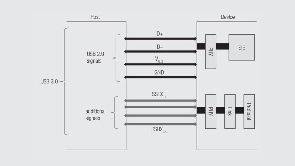
It is beyond the scope of this article to describe the full USB 3.0 architecture in detail. However, it is important to note that it was inspired by the layered PCIe architecture and the OSI model. Therefore, it includes a physical layer (PHY), a link layer and a protocol layer.

RelatedPosts

Polymer Materials and Processing

What is RF Connector

Connector Materials and Processes

Separate data lanes used for up and download enable reading and storing files at the same time and therefore offer a much higher data rate, up to 4.8 Gbits/s (versus 480 Mb/s for USB 2.0).

Power Management
USB 3.0 provides enhanced power management capabilities. With up to 150 mA per unit (+50 % compared to USB 2.0) and up to 6 units together, USB 3.0 can carry up to 900 mA, versus 500 mA with USB 2.0. This means a total 80% increase compared to USB 2.0.

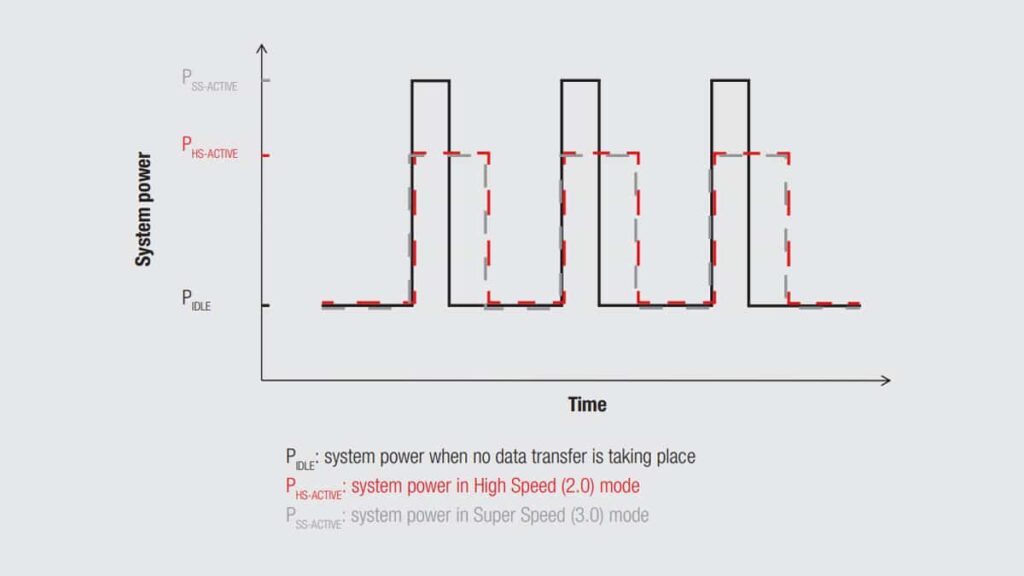
There again, this article does not aim to describe how this works in detail, but it is worth noting that while USB 3.0 requires more power when active, it still consumes less power in the end. Indeed, its higher data rate and various power efficiency features let it remain far less active than in the High-Speed Mode. (See Figure 2.133 which compares power consumption during data transfer in High-Speed and Super-Speed Modes).

Fig. 2.133: Power consumption: comparison between High Speed mode & Super Speed mode

Backward Compatibility
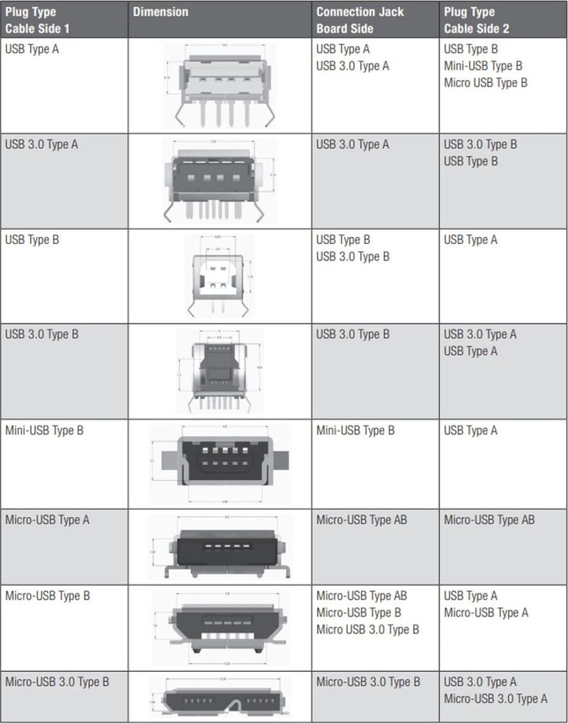
As always with USB, the architecture is designed to ensure the electrical and mechanical backward compatibility with former USB versions (1.1 and 2.0). For example, a USB 3.0 compliant host will communicate with a device at the highest rate supported by the said device. Reciprocally: a USB 3.0 compliant device will function at USB 2.0 rate when plugged into a USB 2.0 host.

Tab. 2.10: USB connectors and mating parts – backwards compatibility from USB 3.0 to USB 2.0

This backward compatibility remains a major advantage compared to all other connection protocols available on the market. Indeed, it avoids obsolescence of existing products extending their life in the field. This is especially true for industrial applications where the life cycle has nothing to do with consumer goods.

Fig. 2.134: Backward compatibility

Related

Source: Wurth elektronik

Recent Posts

Circular Connectors Coding

26.11.2025
36

Connector PCB Design Challenges

3.10.2025
61

Non-Magnetic Interconnects

23.4.2025
30

10 Tips for Ensuring Reliability of Discrete Wire Assemblies

20.2.2025
65

Polymer Materials and Processing

11.8.2025
95

Basic PCB Technology Overview

1.7.2025
30

What is RF Connector

17.12.2024
18

Creepage and Clearance of Connector

25.7.2025
31

Microwave Multi Line Connectors Mounting and Handling Precautions

11.8.2025
9

Upcoming Events

Jan 27
16:00 - 17:00 CET

Simplifying Vehicle Development with Automotive Ethernet and Zonal Smart Switch Technologies

Feb 24
16:00 - 17:00 CET

Designing Qi2 Wireless Power Systems: Practical Development and EMC Optimization

View Calendar

Popular Posts

  • Buck Converter Design and Calculation

    0 shares
    Share 0 Tweet 0
  • Boost Converter Design and Calculation

    0 shares
    Share 0 Tweet 0
  • LLC Resonant Converter Design and Calculation

    0 shares
    Share 0 Tweet 0
  • Flyback Converter Design and Calculation

    0 shares
    Share 0 Tweet 0
  • What Electronics Engineer Needs to Know About Passive Low Pass Filters

    0 shares
    Share 0 Tweet 0
  • Ripple Current and its Effects on the Performance of Capacitors

    3 shares
    Share 3 Tweet 0
  • Dual Active Bridge (DAB) Topology

    0 shares
    Share 0 Tweet 0
  • MLCC and Ceramic Capacitors

    0 shares
    Share 0 Tweet 0
  • SEPIC Converter Design and Calculation

    0 shares
    Share 0 Tweet 0
  • What is a Dielectric Constant and DF of Plastic Materials?

    4 shares
    Share 4 Tweet 0

Newsletter Subscription


Passive Components Blog

© EPCI - Leading Passive Components Educational and Information Site

  • Home
  • Privacy Policy
  • EPCI Membership & Advertisement
  • About

No Result
View All Result
  • Home
  • Knowledge Blog
  • PCNS

© EPCI - Leading Passive Components Educational and Information Site

This website uses cookies. By continuing to use this website you are giving consent to cookies being used. Visit our Privacy and Cookie Policy.
Go to mobile version