Passive Components Blog
No Result
View All Result
  • Home
  • NewsFilter
    • All
    • Aerospace & Defence
    • Antenna
    • Applications
    • Automotive
    • Capacitors
    • Circuit Protection Devices
    • electro-mechanical news
    • Filters
    • Fuses
    • Inductors
    • Industrial
    • Integrated Passives
    • inter-connect news
    • Market & Supply Chain
    • Market Insights
    • Medical
    • Modelling and Simulation
    • New Materials & Supply
    • New Technologies
    • Non-linear Passives
    • Oscillators
    • Passive Sensors News
    • Resistors
    • RF & Microwave
    • Telecommunication
    • Weekly Digest

    Transformer Safety IEC 61558 Standard

    ESR of Capacitors, Measurements and Applications

    Murata Christophe Pottier Appointed President of EPCIA

    3-Phase EMI Filter Design, Simulation, Calculation and Test

    YAGEO Unveils Compact 2.4 GHz SMD Antenna

    KYOCERA AVX Releases Antenna for Iridium Satellite IoT Applications

    Molex Releases Industry-First Quad-Row Board-to-Board Connectors with EMI Shields

    Image credit: Samtec

    How to Match the Right Connector with Protocol Requirements

    Smoltek CNF-MIM Capacitors Pass 1,000h Reliability Test

    Trending Tags

    • Ripple Current
    • RF
    • Leakage Current
    • Tantalum vs Ceramic
    • Snubber
    • Low ESR
    • Feedthrough
    • Derating
    • Dielectric Constant
    • New Products
    • Market Reports
  • VideoFilter
    • All
    • Antenna videos
    • Capacitor videos
    • Circuit Protection Video
    • Filter videos
    • Fuse videos
    • Inductor videos
    • Inter-Connect Video
    • Non-linear passives videos
    • Oscillator videos
    • Passive sensors videos
    • Resistor videos

    Transformer Safety IEC 61558 Standard

    3-Phase EMI Filter Design, Simulation, Calculation and Test

    Transformer Design Optimization for Power Electronics Applications

    Common Mode Chokes Selection for RF Circuits in Next-Generation Communication Systems

    Capacitor Self-balancing in a Flying-Capacitor Buck Converter

    How to Select Ferrite Bead for Filtering in Buck Boost Converter

    Power Inductors Future: Minimal Losses and Compact Designs

    Percolation Phenomenon: Degradation of Molded Power Inductors in DC/DC Converters

    Connector PCB Design Challenges

    Trending Tags

    • Capacitors explained
    • Inductors explained
    • Resistors explained
    • Filters explained
    • Application Video Guidelines
    • EMC
    • New Products
    • Ripple Current
    • Simulation
    • Tantalum vs Ceramic
  • Knowledge Blog
  • Suppliers
    • Who is Who
  • PCNS
    • PCNS 2025
    • PCNS 2023
    • PCNS 2021
    • PCNS 2019
    • PCNS 2017
  • Events
No Result
View All Result
Passive Components Blog
No Result
View All Result

Use LT SPICE to analyze input filters

29.8.2022
Reading Time: 4 mins read
A A

by Kenneth Wyatt. EMC engineers are often called on to design low-pass filters for client projects, which is usually required to meet radiated susceptibility tests. While the most common radiated-immunity standard (IEC/EN 61000-4-3) requires testing from 80 MHz to 1000 MHz, this case study required immunity from a nearby 50 W, 500 kHz source.

In this case, the prototype product included a simple “PI” filter, comprising a parallel 330 pF capacitor, a series ferrite bead, and a parallel 100 pF capacitor. The load was 4.02 kΩ.

RelatedPosts

Transformer Safety IEC 61558 Standard

ESR of Capacitors, Measurements and Applications

Murata Christophe Pottier Appointed President of EPCIA

Figure 1. Basic filter topologies chart. (Source: Würth Electronik)

I thought this would be a good time to use Linear Technology’s free LT SPICE software to perform some quick simulations. LT SPICE is a PC-based analysis software with a convenient schematic entry front-end. It’s also very easy to add voltage and current “probes” throughput your circuit to monitor the performance.

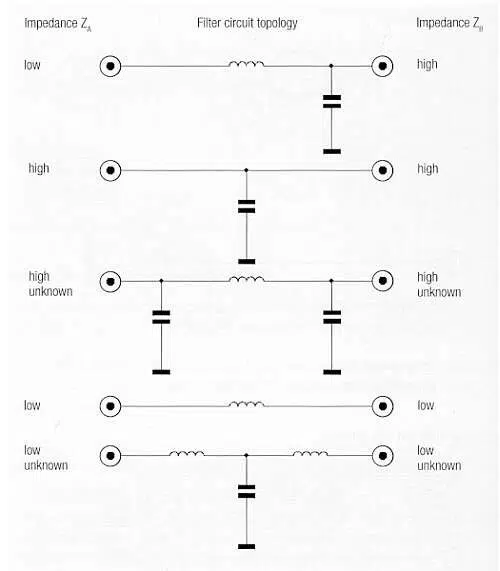
But first, which of the several filter topologies would be most appropriate? Würth Electronik has a very nice filter design section in its book, Trilogy of Magnetics. It turns out the right filter topology depends on the input and out impedances of the system. I’ve reproduced a handy chart (Figure 1) from page 184 of the book that you should copy and tuck into your lab notebook.

For the series filter impedance (the ferrite bead, in this case) to work, it must “see” a low impedance at each end. For example, placing a 200 Ω ferrite bead into a system with 1000 Ω and 4 kΩ input-and-output impedances wouldn’t offer sufficient series impedance to affect interfering signals. On the other hand, that same 200 Ω ferrite would work fine if the input and output impedances were near 1 Ω. That’s the purpose of the parallel capacitors.

In this case, the input impedance to the filter could vary, depending on the sensor impedance, and we knew the output impedance was 4.02 kΩ. The designer had already used a PI filter topology, which should perform well for any impedance from low to high, per the chart.

Figure 2. The input filter to be analyzed.

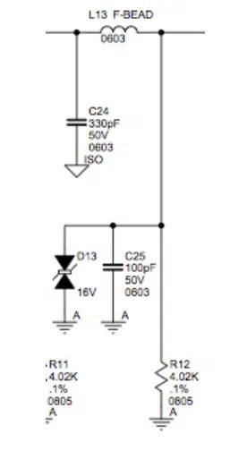
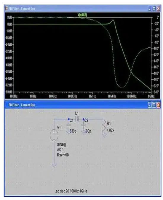
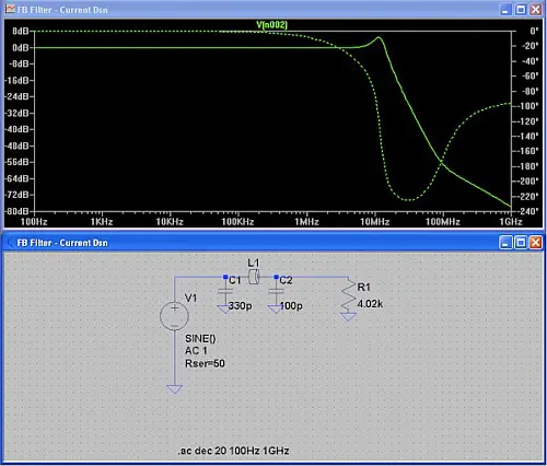
Here’s the original input filter circuit (Figure 2). For the purposes of this simulation, I ignored the Transzorb® D13. The input is on the left and output on the right.

By inspection, I could tell the current values of capacitors were way too small to provide a low impedance to ground for a frequency of 500 kHz, so the first thing I tried was to increase them to 0.47 µF, each. But first, let’s simulate the current circuit to see where the impedance starts to roll off.

Here’s the LT SPICE simulation (Figure 3). I used an input impedance of 50 Ω, but with the proper valued capacitor, it really doesn’t matter much. Note that the 3 dB rolloff (solid line) occurs about 16 MHz; way too high to help at 500 kHz.

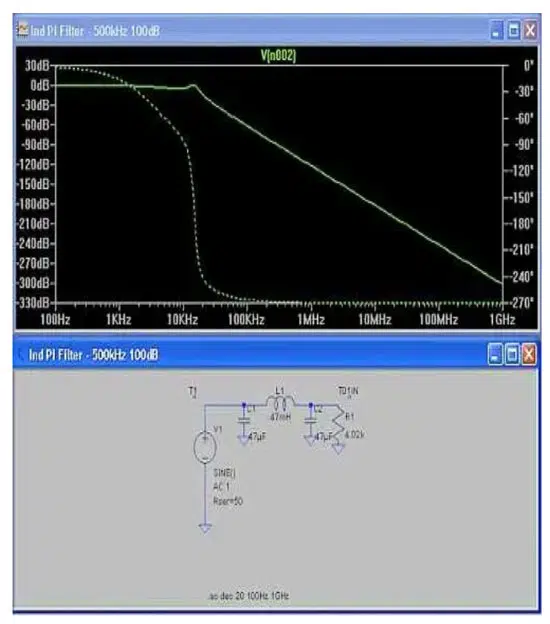
Here’s the final LT SPICE simulation with 0.47 µF capacitors and the ferrite replaced with a 0.47 mH inductor (Figure 4). Note the improved filter starts rolling off at 20 kHz — well below the critical 500 kHz interfering signal and provides about 90 dB of attenuation at 500 kHz. The client was able to use the same real estate on the PC board to mount the new components. While there were other circuit changes and better shielding required, due to the proximity of the source, the filter reduced the high level of interference.

Figure 3. Initial SPICE analysis of the current filter circuit.
Figure 4. Final SPICE analysis of the improved filter circuit.

Related

Source: EDN

Recent Posts

Transformer Safety IEC 61558 Standard

7.11.2025
1

ESR of Capacitors, Measurements and Applications

7.11.2025
10

3-Phase EMI Filter Design, Simulation, Calculation and Test

6.11.2025
23
Image credit: Samtec

How to Match the Right Connector with Protocol Requirements

6.11.2025
12

Coilcraft Introduces Ultra-Low Loss Shielded Power Inductors

6.11.2025
13

Exxelia Presents Smart Integrated Magnetics Solution at Space Tech Expo 2025 

5.11.2025
15

Murata Expands High Cutoff Frequency Chip Common Mode Chokes

5.11.2025
9

Transformer Design Optimization for Power Electronics Applications

4.11.2025
20

Microhardness — the Hidden Key to Understanding MnOx Cathode Quality in Tantalum Capacitors

3.11.2025
23

Lightweight Model for MLCC Appearance Defect Detection

3.11.2025
25

Upcoming Events

Nov 11
17:00 - 18:00 CET

Industrial Applications Demand More from Interconnects in Next-Gen Designs

Nov 12
11:00 - 12:00 CET

PCB Design: Impedance is for everyone!

Nov 12
November 12 @ 12:00 - November 13 @ 14:15 EST

Microelectronic Packaging Failure Modes and Analysis

View Calendar

Popular Posts

  • Buck Converter Design and Calculation

    0 shares
    Share 0 Tweet 0
  • Boost Converter Design and Calculation

    0 shares
    Share 0 Tweet 0
  • LLC Resonant Converter Design and Calculation

    0 shares
    Share 0 Tweet 0
  • Flyback Converter Design and Calculation

    0 shares
    Share 0 Tweet 0
  • Ripple Current and its Effects on the Performance of Capacitors

    3 shares
    Share 3 Tweet 0
  • MLCC and Ceramic Capacitors

    0 shares
    Share 0 Tweet 0
  • Dual Active Bridge (DAB) Topology

    0 shares
    Share 0 Tweet 0
  • What is a Dielectric Constant and DF of Plastic Materials?

    4 shares
    Share 4 Tweet 0
  • SEPIC Converter Design and Calculation

    0 shares
    Share 0 Tweet 0
  • Flying Capacitors

    0 shares
    Share 0 Tweet 0

Newsletter Subscription


Passive Components Blog

© EPCI - Leading Passive Components Educational and Information Site

  • Home
  • Privacy Policy
  • EPCI Membership & Advertisement
  • About

No Result
View All Result
  • Home
  • Knowledge Blog
  • PCNS

© EPCI - Leading Passive Components Educational and Information Site

This website uses cookies. By continuing to use this website you are giving consent to cookies being used. Visit our Privacy and Cookie Policy.
Go to mobile version