Passive Components Blog
No Result
View All Result
  • Home
  • NewsFilter
    • All
    • Aerospace & Defence
    • Antenna
    • Applications
    • Automotive
    • Capacitors
    • Circuit Protection Devices
    • electro-mechanical news
    • Filters
    • Fuses
    • Inductors
    • Industrial
    • Integrated Passives
    • inter-connect news
    • Market & Supply Chain
    • Market Insights
    • Medical
    • Modelling and Simulation
    • New Materials & Supply
    • New Technologies
    • Non-linear Passives
    • Oscillators
    • Passive Sensors News
    • Resistors
    • RF & Microwave
    • Telecommunication
    • Weekly Digest

    Overvoltage and Transient Protection for DC/DC Power Modules

    Choosing the Right Capacitor: The Importance of Accurate Measurements

    Littelfuse Releases TMR Switches with Ultra-Low Power Magnetic Sensing

    Skeleton Opens SuperBattery Factory in Finland 

    Kyocera Releases Ultra-Compact Low Voltage Clock Oscillators

    Murata Expands High Rel NTC Thermistors in Compact 0603M Size

    RF Inductors: Selection and Design Challenges for High-Frequency Circuits

    Wk 45 Electronics Supply Chain Digest

    Transformer Safety IEC 61558 Standard

    Trending Tags

    • Ripple Current
    • RF
    • Leakage Current
    • Tantalum vs Ceramic
    • Snubber
    • Low ESR
    • Feedthrough
    • Derating
    • Dielectric Constant
    • New Products
    • Market Reports
  • VideoFilter
    • All
    • Antenna videos
    • Capacitor videos
    • Circuit Protection Video
    • Filter videos
    • Fuse videos
    • Inductor videos
    • Inter-Connect Video
    • Non-linear passives videos
    • Oscillator videos
    • Passive sensors videos
    • Resistor videos

    Choosing the Right Capacitor: The Importance of Accurate Measurements

    RF Inductors: Selection and Design Challenges for High-Frequency Circuits

    Transformer Safety IEC 61558 Standard

    3-Phase EMI Filter Design, Simulation, Calculation and Test

    Transformer Design Optimization for Power Electronics Applications

    Common Mode Chokes Selection for RF Circuits in Next-Generation Communication Systems

    Capacitor Self-balancing in a Flying-Capacitor Buck Converter

    How to Select Ferrite Bead for Filtering in Buck Boost Converter

    Power Inductors Future: Minimal Losses and Compact Designs

    Trending Tags

    • Capacitors explained
    • Inductors explained
    • Resistors explained
    • Filters explained
    • Application Video Guidelines
    • EMC
    • New Products
    • Ripple Current
    • Simulation
    • Tantalum vs Ceramic
  • Knowledge Blog
  • Suppliers
    • Who is Who
  • PCNS
    • PCNS 2025
    • PCNS 2023
    • PCNS 2021
    • PCNS 2019
    • PCNS 2017
  • Events
No Result
View All Result
Passive Components Blog
No Result
View All Result

What Do You Need to Know About Bypassing

24.8.2022
Reading Time: 3 mins read
A A

Source: Electronic Design article

by Lou Frenzel. The seemingly ubiquitous bypass capacitor is an important component in design, especially when dealing with high frequencies. But what’s the driving force behind its usage?

RelatedPosts

Overvoltage and Transient Protection for DC/DC Power Modules

Choosing the Right Capacitor: The Importance of Accurate Measurements

Littelfuse Releases TMR Switches with Ultra-Low Power Magnetic Sensing

Just recently, I was eavesdropping on several engineer acquaintances of mine discussing bypass capacitors. Also known as decoupling capacitors, these capacitors are everywhere. Some products contain hundreds of capacitors, many of which are bypass capacitors. That got me to thinking: “How much do most engineers actually know about bypassing?” It’s probably not something you learned in school.

As engineers, many of us probably learned bypassing/decoupling by observing what others have done; that is, just put a 0.1-µF ceramic capacitor on each IC power connection and be done with it. That seems to work in many designs. But as it turns out, there’s a bit more to it than that. With MCUs and other digital circuitry running many megahertz or even gigahertz, the noise they generate is a problem. And the use of switch-mode power supplies (SMPS) contributes to the noise. Therefore, we bypass.

The problem arises mainly from the need for one dc supply to furnish voltage to multiple ICs on a printed circuit board (PCB) or across multiple PCBs. The power supply, and each attached circuit, generate some noise, high current transients, or whatever. These get passed around via the common dc power connection and other conducted means. This isn’t good. The traditional approach is to add a low-pass filter at each IC power connection. Isn’t that what bypassing is?

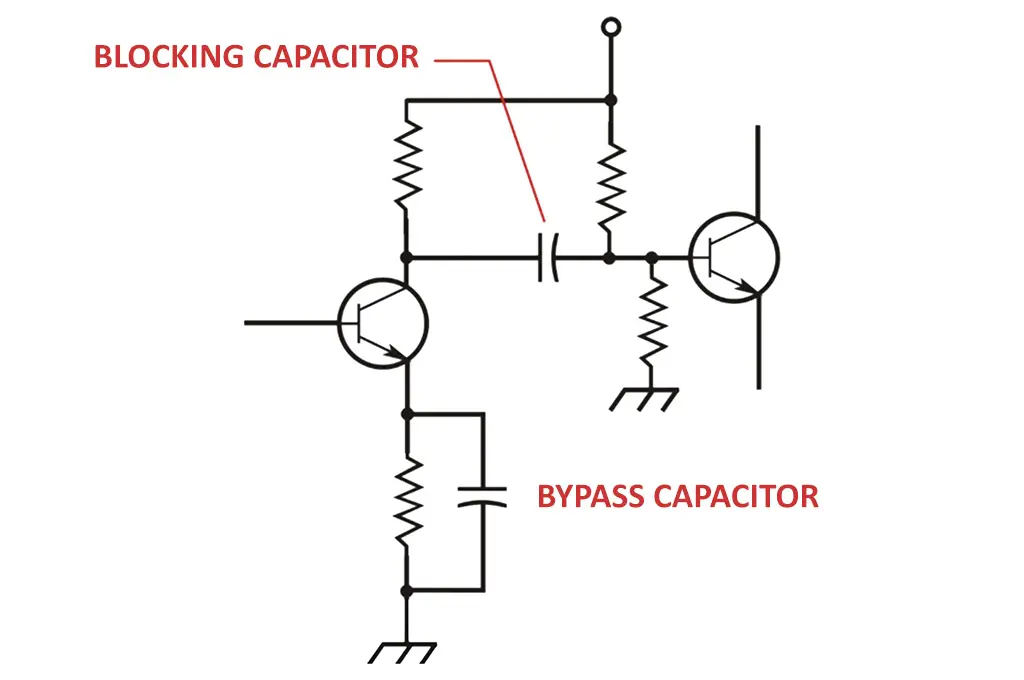
The basic solution in serious cases is to add multiple bypass capacitors to deal with the various types of noise. Since capacitors store a charge, they can minimize dc power-supply transients. Capacitors are supposed to smooth the dc supply output so that it looks like a clean horizontal line on the scope screen. Well, almost. Capacitors also provide a low impedance path to ground for unwanted high-frequency noise signals.

High-Frequency Equipment Designs

The need for effective bypassing really shows up when designing equipment operating at very high frequencies, like 50 MHz and above. At these frequencies, any stray or distributed inductance or the parasitic inductance of a capacitor become major impedances. Long connecting wires, long PCB traces, and the parasitic inductance in the capacitors help distribute all the noise around to the various ICs connected to the power supply.

Consequently, the first part of the solution is to minimize this inductance by reducing cable lengths and making PCB traces short. Luckily, many designs are being implemented on very small boards, so the trace inductance isn’t too much of a problem. Then, as you undoubtedly learned from experience, put a bypass capacitor on the power pin of each IC. And that means soldering the capacitor right on the pin itself to reduce any inductance between the supply and the IC.

For best results, you should experiment with the value of that capacitor. While the traditional 0.1-µF capacitor usually works, you should test different values while observing the noise on the power pin on your scope. In some cases, you may only need 0.01 µF or 0.001 µF—even mid to high pF will do the job. In some products, one bypass capacitor per chip isn’t needed. It may be a case of overkill. Nevertheless, if you can afford the minor extra expense, don’t take any chances. Bypass everything in sight. Experiment. Every design is different.

Don’t Skimp on Quality

The quality of the capacitor is another issue. Its equivalent series resistance (ESR) is a major factor in high-frequency bypassing. In many low-frequency designs, we ignore the ESR, and in bypassing, it’s an often-overlooked factor. Another typically ignored characteristic is equivalent series inductance (ESL). It too is a capacitor parasitic. While the ESL is very low (pH), it can affect the bypassing. The issue is that at some frequency, the capacitor becomes self-resonant. When triggered by noise or pulses, the capacitor oscillates or rings.

A common solution is to put two or more different-sized bypass capacitors in parallel, thereby making the lowest possible overall impedance. The use of multiple parallel bypass capacitors will minimize the effect of the parasitics in the capacitors. Remember to design the PCB layout to accommodate multiple bypass capacitors, in parallel.

As for what type of capacitor to use, your best bet is ceramic. It has a very low ESR and ESL and comes in a wide range of values. Mica capacitors have even lower ESR/ESL, but these are very expensive. The ceramic capacitors are available in most of the standard SMD sizes. And they’re cheap.

Of course, the standard practice of decoupling the PCB from the dc supply is still a good idea. Use an electrolytic on the board where the dc power enters the board. 10 µF is common, but a lower value may work. A good alternative is large ceramic capacitor too.

So, what you probably already knew is correct—a big capacitor to decouple the board from the dc source and small capacitors on each chip. Use multiple parallel capacitors at the higher frequencies. Don’t just dismiss bypassing. Fine-tune it to your design by really understanding what’s going on.


Related

Recent Posts

Overvoltage and Transient Protection for DC/DC Power Modules

13.11.2025
4

Choosing the Right Capacitor: The Importance of Accurate Measurements

12.11.2025
17

Skeleton Opens SuperBattery Factory in Finland 

12.11.2025
10

RF Inductors: Selection and Design Challenges for High-Frequency Circuits

10.11.2025
37

Transformer Safety IEC 61558 Standard

7.11.2025
15

ESR of Capacitors, Measurements and Applications

7.11.2025
70

3-Phase EMI Filter Design, Simulation, Calculation and Test

6.11.2025
67
Image credit: Samtec

How to Match the Right Connector with Protocol Requirements

6.11.2025
18

Smoltek CNF-MIM Capacitors Pass 1,000h Reliability Test

6.11.2025
13

Upcoming Events

Dec 2
December 2 @ 12:00 - December 4 @ 14:15 CET

Microwave Packaging Technology

Dec 9
December 9 @ 12:00 - December 11 @ 14:15 EST

Space and Military Standards for Hybrids and RF Microwave Modules

Dec 10
16:00 - 17:00 CET

Designing Qi2 Wireless Power Systems: Practical Development and EMC Optimization

View Calendar

Popular Posts

  • Buck Converter Design and Calculation

    0 shares
    Share 0 Tweet 0
  • Boost Converter Design and Calculation

    0 shares
    Share 0 Tweet 0
  • Flyback Converter Design and Calculation

    0 shares
    Share 0 Tweet 0
  • LLC Resonant Converter Design and Calculation

    0 shares
    Share 0 Tweet 0
  • Ripple Current and its Effects on the Performance of Capacitors

    3 shares
    Share 3 Tweet 0
  • Dual Active Bridge (DAB) Topology

    0 shares
    Share 0 Tweet 0
  • MLCC and Ceramic Capacitors

    0 shares
    Share 0 Tweet 0
  • What is a Dielectric Constant and DF of Plastic Materials?

    4 shares
    Share 4 Tweet 0
  • SEPIC Converter Design and Calculation

    0 shares
    Share 0 Tweet 0
  • What Electronics Engineer Needs to Know About Passive Low Pass Filters

    0 shares
    Share 0 Tweet 0

Newsletter Subscription


Passive Components Blog

© EPCI - Leading Passive Components Educational and Information Site

  • Home
  • Privacy Policy
  • EPCI Membership & Advertisement
  • About

No Result
View All Result
  • Home
  • Knowledge Blog
  • PCNS

© EPCI - Leading Passive Components Educational and Information Site

This website uses cookies. By continuing to use this website you are giving consent to cookies being used. Visit our Privacy and Cookie Policy.
Go to mobile version