Passive Components Blog
No Result
View All Result
  • Home
  • NewsFilter
    • All
    • Aerospace & Defence
    • Antenna
    • Applications
    • Automotive
    • Capacitors
    • Circuit Protection Devices
    • electro-mechanical news
    • Filters
    • Fuses
    • Inductors
    • Industrial
    • Integrated Passives
    • inter-connect news
    • Market & Supply Chain
    • Market Insights
    • Medical
    • Modelling and Simulation
    • New Materials & Supply
    • New Technologies
    • Non-linear Passives
    • Oscillators
    • Passive Sensors News
    • Resistors
    • RF & Microwave
    • Telecommunication
    • Weekly Digest

    Modeling and Simulation of Leakage Inductance

    Power Inductor Considerations for AI High Power Computing – Vishay Video

    TAIYO YUDEN Releases Compact SMD Power Inductors for Automotive Application

    Fischer Releases High Vibration Robust Ratchet Locking USB-C Connector System

    Littelfuse Unveils High-Use Tactile Switches with 2 Million Cycle Lifespan

    KYOCERA AVX Releases Compact High-Directivity Couplers

    Supercapacitors Emerge as a Promising Solution to AI-Induced Power Energy Spikes

    Wk 18 Electronics Supply Chain Digest

    YAGEO Releases High Current SMD Common Mode Choke With Shape Core Construction

    Trending Tags

    • Ripple Current
    • RF
    • Leakage Current
    • Tantalum vs Ceramic
    • Snubber
    • Low ESR
    • Feedthrough
    • Derating
    • Dielectric Constant
    • New Products
    • Market Reports
  • VideoFilter
    • All
    • Antenna videos
    • Capacitor videos
    • Circuit Protection Video
    • Filter videos
    • Fuse videos
    • Inductor videos
    • Inter-Connect Video
    • Non-linear passives videos
    • Oscillator videos
    • Passive sensors videos
    • Resistor videos

    Modeling and Simulation of Leakage Inductance

    Power Inductor Considerations for AI High Power Computing – Vishay Video

    Coupled Inductors in Multiphase Boost Converters

    VPG Demonstrates Precision Resistor in Cryogenic Conditions

    Comparison Testing of Chip Resistor Technologies Under High Vibration

    EMC Challenges for High Speed Signal Immunity and Low EMI

    MOSFET Gate Drive Resistors Power Losses

    Modified Magnetic Reluctance Equivalent Circuit and its Implications

    Improving Common Mode Noise Reduction while Decreasing BOM

    Trending Tags

    • Capacitors explained
    • Inductors explained
    • Resistors explained
    • Filters explained
    • Application Video Guidelines
    • EMC
    • New Products
    • Ripple Current
    • Simulation
    • Tantalum vs Ceramic
  • Knowledge Blog
  • Suppliers
    • Who is Who
  • Events
No Result
View All Result
Passive Components Blog
No Result
View All Result

Wide Terminal Reverse Geometry Chip Resistors Boost Power Rating and Mechanical Robustness

30.6.2021
Reading Time: 5 mins read
A A

A higher level of power in smaller parts – this is undoubtedly the overriding direction where the electronic component market is currently heading. This article explains construction and advantage of wide terminal (reverse geometry) resistor chips.

Chip resistors, being one of the smallest and most accessible components in any electronic design. When looking, for instance, at a standard resistor in 1206 case size with a power range of 0.25W, there is a constant demand from the market to achieve this range in a case size not larger than 0603.

RelatedPosts

Panasonic Expands Production of Hybrid Capacitors for AI

Panasonic Industry Extends OS-CON High-Voltage Aluminum Capacitors

Panasonic Extends Polarized Power Relays for Smart Lighting and IoT Applications

For established suppliers of high quality resistors, this means to continuously strive for innovation in order to meet the customers’ demands for a contemporarily advanced resistor portfolio. One of the key approach for meeting those resistor downsizing requirements would be the wide terminal resistors.

Figure 1: wide terminal chip resistors design; source: Panasonic

Wide Termination Resistors Construction

The name is based on two innovative constructive principles:

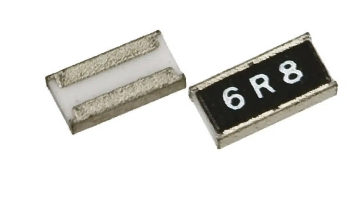
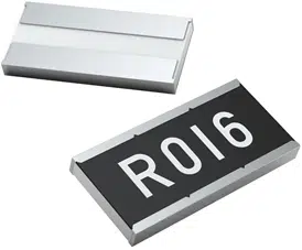
  1. The terminals on this type of resistor are found on the long side of the resistor whereas they are on the short one at conventional products (see Figure 1). So, when having conventionally a 2010 case size, the wide terminal type would be correspondingly 1020 case size. This increases the amount of current being able to pass through the resistor which results in a significantly higher power range.
  2. Instead of using one block of resistive element, two or three blocks can be used.

Benefits of wide termination designs

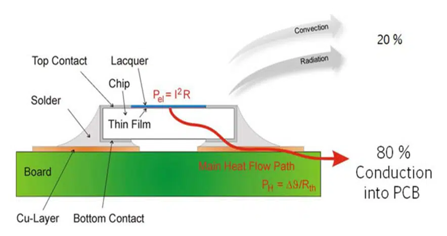
  • better thermal conduction into PCB = higher power rating by 30-50% (Figure 2.)
  • lower ESL = lower parasitic and higher frequency range (Figure 3.)
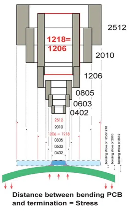
  • higher mechanical strength = higher vibration and flex stress robustness (Figure 3.)
  • less thermal stress as differences in the coefficient of expansion between substrate and chip decreases in significance with shorter distances between terminations
Figure 2. Wide termination designs increase power ratings by 30-50% due to better thermal conduction into PCB; source: KOA
Figure 3. Wide terminal vibration / flex robustness and lower ESL; source: AVX

Is there any trade off using reverse geometry wide terminal devices? The only downside of the design, considering the high manufacturing price is now almost identical, that PCB cleaning process may be more difficult in narrow and long gaps between the termination pads.

Using of multiple resistive element blocks

Using of multiple (typically two or three depending to case size) instead of one block of resistive elements may further increase wide termination resistor chips’ thermal dissipation ability and thus increase the power rating even further. Each of these smaller elements is trimmed by laser. This supports the heat dissipation throughout the alumina substrate elements and avoids hotspots in one area. See figure 4.

Figure 4. Heat generation comparison of two resistive elements vs single element; source: Panasonic

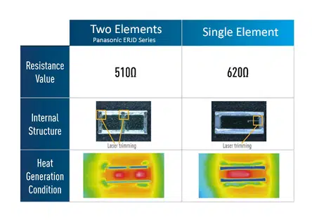
As a result, the power range can be increased.

Applications

The field of suitable applications for wide terminal resistors is wide: From automotive and industrial applications to building automation and many other applications where a higher power range is as essential as a compact case design.

Wide terminal resistors with lower resistance values are particularly popular for replacing metal shunt resistors. If the replacement is technically feasible, resorting to these resistors helps saving space on the PCB. Wide terminal resistors are much cheaper compared to metal shunt resistors, rendering them the perfect solution for current sensing with higher power requirements.

In the automotive sector, wide terminal resistors can be used in electrical control units (ECU), anti-lock braking systems, headlights, EPS, motors and many other applications whereas in industrial contexts, wide terminal resistors are the perfect solution for power supplies, DC/DC converters or motor controls.

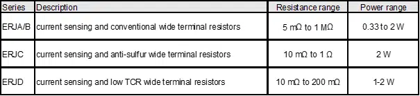
See Figure 5. with example of available types and range.

Figure 5. Example of wide termination chip resistor types, and range; source: Panasonic

Summary

Wide terminal, reverse geometry chip resistors present a set of benefits over conventional designs. Electronic designers shall look into these type of components especially when searching for resistor downsizing without any compromises in terms of power handling.

In addition, wide terminal designs provide higher mechanical vibration and flex robustness that is often required in automotive, industrial or aerospace applications. Lower ESL values helps also to improve its operating frequency range.

Use of multiple resistive elements inside of the wide resistor chip body may increase power rating even higher.

Related

Source: Panasonic Industry, EPCI

Recent Posts

Modeling and Simulation of Leakage Inductance

9.5.2025
1

TAIYO YUDEN Releases Compact SMD Power Inductors for Automotive Application

9.5.2025
1

Fischer Releases High Vibration Robust Ratchet Locking USB-C Connector System

9.5.2025
1

KYOCERA AVX Releases Compact High-Directivity Couplers

7.5.2025
15

Murata and NIMS Built New Database of Dielectric Material Properties

5.5.2025
43

Tariffs Crush Sales Sentiment in April 2025 ECST Results

5.5.2025
59

High-Density PCB Assemblies For Space Applications

2.5.2025
7

Solid State Polymer Multilayer Capacitors For High Temperature Application

2.5.2025
29

Graphene-Based BOSC Bank Of Supercapacitor Cells

2.5.2025
13

W-band Self-Biased Circulators for Next Gen VHTS Satellites

1.5.2025
3

Upcoming Events

May 14
11:00 - 12:00 CEST

Reliable RIGID.flex PCBs for Critical Applications – Made in Europe

May 28
16:00 - 17:00 CEST

Power Over Data Line

View Calendar

Popular Posts

  • Buck Converter Design and Calculation

    0 shares
    Share 0 Tweet 0
  • Boost Converter Design and Calculation

    0 shares
    Share 0 Tweet 0
  • Tariffs Crush Sales Sentiment in April 2025 ECST Results

    0 shares
    Share 0 Tweet 0
  • Flyback Converter Design and Calculation

    0 shares
    Share 0 Tweet 0
  • LLC Resonant Converter Design and Calculation

    0 shares
    Share 0 Tweet 0
  • Dual Active Bridge (DAB) Topology Explained

    0 shares
    Share 0 Tweet 0
  • What is a Dielectric Constant and DF of Plastic Materials?

    4 shares
    Share 4 Tweet 0
  • SEPIC Converter Design and Calculation

    0 shares
    Share 0 Tweet 0
  • Ripple Current and its Effects on the Performance of Capacitors

    3 shares
    Share 3 Tweet 0
  • Flying Capacitors Explained

    0 shares
    Share 0 Tweet 0

Newsletter Subscription


Passive Components Blog

© EPCI - Leading Passive Components Educational and Information Site

  • Home
  • Privacy Policy
  • EPCI Membership & Advertisement
  • About

No Result
View All Result
  • Home
  • Knowledge Blog
  • Premium Suppliers

© EPCI - Leading Passive Components Educational and Information Site

This website uses cookies. By continuing to use this website you are giving consent to cookies being used. Visit our Privacy and Cookie Policy.
Go to mobile version