The range fear still represents an obstacle to the widespread acceptance of electric vehicles. Two things that can overcome the resistance to new technologies are common sense and technical improvements. Patrik Kalbermatten, senior manager of MSABG (Magnetic, Sensor and Actuator) division at Kemet discuss importance of wireless charging at his article published and edited by elektroniknet.de
As for common sense, electric mobility supporters point out that the typical daily mileage, which includes commuting to work and doing shopping, is, on average, quite low. Typical daily journeys are easy to manage with most of the electric cars currently on the market. This might convince potential buyers who are already interested in switching to an electric car. With other drivers, however, more persuasive work is necessary, and this can best be done through further technical advances.
Fast and easy charging
For days when additional errands or a longer drive are required, or to be prepared for an emergency, it makes sense to have a few kilometers on reserve. Faster loading could help. Every electric vehicle can be charged using a simple level 1 charger that is plugged into a normal socket and provides up to 1 kW of power. However, if you want to achieve an additional range of 150 km, this can take almost 20 hours (table).
| step | power | approximate charging time (empty battery) |
|---|---|---|
| 1 | 1 kW | 200 km: +/- 20 hours 400 km: +/- 43 hours |
| 2 | 3 to 20 kW, typ. 6 kW | 200 km: +/- 5 hours 400 km: +/- 11 hours |
| 3 (DCFC) | typ. 50 kW, occasionally 20 kW | 80% of 200 km: +/- 30 min |
Table: Comparison of charging times for wired standard charging points (Level 1 to 3) (Source: https://chargehub.com/en/electric-car-charging-guide.html)
Level 2 charging stations with an output of up to 20 kW are installed on the roadside, in inner-city parking lots and optionally also by private users at home. They can usually transfer comparable energy in a quarter of the time or less. Level 3 charging stations of level 3 or DC fast chargers (DCFC, DC Fast Chargers) are the most powerful and therefore fastest charging types. However, they are not available at all public charging stations and are not suitable for all electric vehicles.
In order for drivers to be able to charge their vehicle battery on one of these charger types, they have to find a suitable charging parking space, get the charging cable out of the car, plug it in and wait.
Add wireless charging to the charging mix
As part of the charging mix, wireless charging could make charging more convenient and help overcome potential customers’ range fears. Wireless charging of electric vehicles relies on resonant magnetic induction to transfer energy between a charging pad in the floor and another pad on the underside of the vehicle. A typical charging pad is around one square meter in size, while the receiving pad is built into a more compact housing on the underside of the vehicle.
Once the two are aligned and coupled together, charging can occur at rates from 3.3 to 20 kW of power.
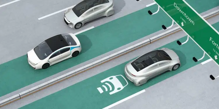
A suitable wireless power transmitter can be embedded in the road surface. It recognizes when a vehicle is above it. The charging process is then started when the vehicle arrives and terminated without further intervention by the driver when it drives away. By setting up a suitable WEVCS (Wireless Electric Vehicle Charging System) infrastructure, it would be possible to gradually charge the electric vehicle every time it stops for a short time – for example when stopping at a supermarket.
A dynamic WEVCS (D-WEVCS) would also be conceivable. This could include highway sections with embedded charging transmitters that charge the batteries of passing vehicles while driving. Dynamic charging is an effective solution, especially for taxis or buses when charging is possible at certain points along the route or while waiting at stops or pick-up / drop-off points.
Figure 1 describes the most important function blocks of a static or dynamic WEVCS. The transmitter is in a fixed position and is powered by an AC power supply of 50 to 60 Hz. After rectification and power factor correction, an inverter generates an output alternating current of 80 to 160 kHz, which is transmitted to the wireless power transmitter coil.
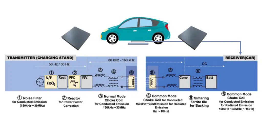
1 = noise filter for conducted emission;
2 = choke for power factor correction;
3 = normal mode choke coil;
4 = common mode choke coil;
5 = sintered ferrite carrier;
6 = common mode choke coil.
The diagram also shows the positions of the input noise filter for conducted interference, the PFC choke, and the normal mode and common mode chokes for conducted and radiated emissions. The power emitted by the transmitter is coupled into the receiver coil, which is attached to the underside of the vehicle. Normal-mode and common-mode filters as well as an AC / DC converter generate a stable DC supply for charging the battery, which is controlled by a battery management system (BMS).
Optimize WEVCS technology
Reliability and energy efficiency are two major challenges for developers in this area. Both the permanently installed transmitter and the receiver mounted on the vehicle can be exposed to extreme temperatures, humidity and physical forces. Kemet helps address these challenges, for example with its environmentally resistant chokes and filters specifically designed for EV charging applications. With new materials that enable the development of more compact components, the size and weight of the system mounted on the vehicle can also be reduced.
In the inverter and AC / DC converter of the transmitter or receiver, power semiconductors with a large band gap (WBG, Wide Band-Gap) and suitable nominal voltage enable efficient power conversion at the wireless power transmission frequency. This ensures sufficient security.
In addition to the WBG semiconductors, ceramic capacitors are required that have a high capacity stability over the entire temperature and voltage range. As a result, the power semiconductors withstand very high ripple currents. A special dielectric system, which enables a very low equivalent series resistance (ESR) and thermal resistance, allows the capacitors to be placed close to the fast-switching semiconductors. As a result, the WEVCS modules achieve a high power density and reliable performance.
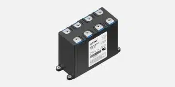
The multilayer ceramic capacitors (MLCCs) of the KC-Link series from Kemet are based on a specially developed, robust C0G / NPO-BME dielectric (base metal electrode), which guarantees a low ESR with high thermal stability. Due to the high mechanical robustness of the capacitors, a structure can be implemented without a leadframe. This reduces the effective series inductance (ESL) and allows a larger operating frequency range and thus further miniaturization.
In order to optimize the efficiency of the power transmission, attention must also be paid to the inductive coupling between the transmitter and receiver coils. The coil design and layout can be improved to reduce dependency on the orientation of the transmitter and receiver. Due to traffic obstacles or road structures, it can happen that a driver or an autonomous driving system cannot position the vehicle perfectly over the transmitter.
However, the position of a movable receiver coil can be fine-tuned and thus the alignment can be optimized. Charging up to 5 kW with an efficiency of over 90% is possible. An air gap of around 150 to 300 mm is usually considered ideal. A lifting or lowering mechanism for the pad on the electric vehicle can be considered in order to compensate for the sometimes considerable differences in ground clearance.
In addition, the application of shielding materials around the power transmitter and the on-board receiver can further increase the efficiency of the energy transfer. Kemet has developed highly permeable sintered ferrite plates that minimize magnetic flux losses and are qualified for automotive applications in accordance with AEC-Q200.
The author
Patrik Kalbermatten is Senior Manager – Distribution Promotion Product Management MSABG (Magnetic, Sensor and Actuator) – at Kemet. After studying at the University Institute for International Studies and Development in Geneva, he gained 13 years of experience in the electronics industry – in sales, distribution, marketing and product management.


