Passive Components Blog
No Result
View All Result
  • Home
  • NewsFilter
    • All
    • Aerospace & Defence
    • Antenna
    • Applications
    • Automotive
    • Capacitors
    • Circuit Protection Devices
    • electro-mechanical news
    • Filters
    • Fuses
    • Inductors
    • Industrial
    • Integrated Passives
    • inter-connect news
    • Market & Supply Chain
    • Market Insights
    • Medical
    • Modelling and Simulation
    • New Materials & Supply
    • New Technologies
    • Non-linear Passives
    • Oscillators
    • Passive Sensors News
    • Resistors
    • RF & Microwave
    • Telecommunication
    • Weekly Digest

    Bourns Extends Rotational Life Option for its Guitar Potentiometer

    Modeling and Simulation of Leakage Inductance

    Power Inductor Considerations for AI High Power Computing – Vishay Video

    TAIYO YUDEN Releases Compact SMD Power Inductors for Automotive Application

    Fischer Releases High Vibration Robust Ratchet Locking USB-C Connector System

    Littelfuse Unveils High-Use Tactile Switches with 2 Million Cycle Lifespan

    KYOCERA AVX Releases Compact High-Directivity Couplers

    Supercapacitors Emerge as a Promising Solution to AI-Induced Power Energy Spikes

    Wk 18 Electronics Supply Chain Digest

    Trending Tags

    • Ripple Current
    • RF
    • Leakage Current
    • Tantalum vs Ceramic
    • Snubber
    • Low ESR
    • Feedthrough
    • Derating
    • Dielectric Constant
    • New Products
    • Market Reports
  • VideoFilter
    • All
    • Antenna videos
    • Capacitor videos
    • Circuit Protection Video
    • Filter videos
    • Fuse videos
    • Inductor videos
    • Inter-Connect Video
    • Non-linear passives videos
    • Oscillator videos
    • Passive sensors videos
    • Resistor videos

    Modeling and Simulation of Leakage Inductance

    Power Inductor Considerations for AI High Power Computing – Vishay Video

    Coupled Inductors in Multiphase Boost Converters

    VPG Demonstrates Precision Resistor in Cryogenic Conditions

    Comparison Testing of Chip Resistor Technologies Under High Vibration

    EMC Challenges for High Speed Signal Immunity and Low EMI

    MOSFET Gate Drive Resistors Power Losses

    Modified Magnetic Reluctance Equivalent Circuit and its Implications

    Improving Common Mode Noise Reduction while Decreasing BOM

    Trending Tags

    • Capacitors explained
    • Inductors explained
    • Resistors explained
    • Filters explained
    • Application Video Guidelines
    • EMC
    • New Products
    • Ripple Current
    • Simulation
    • Tantalum vs Ceramic
  • Knowledge Blog
  • Suppliers
    • Who is Who
  • Events
No Result
View All Result
Passive Components Blog
No Result
View All Result

Waveguides and Transmission Lines Explained

23.6.2022
Reading Time: 4 mins read
A A

This blog article from Knowles Precision Devices explains background information on how waveguides and transmission line filters do what they do.

Two important methods for propagating electromagnetic waves around a circuit are waveguides and transmission lines. At a high level, the main difference between these two methods is the number of conductors involved and the types of electromagnetic modes supported. Let’s explore how these types of electromagnetic modes work and how they are supported, or not supported, by waveguides and transmission lines.

RelatedPosts

RF Inductors Key Characteristics and Applications

Stacked Ceramic Capacitors Improve Efficiency in Power and RF Applications

Capacitors in Pulse Forming Network

Three Types of Electromagnetic Modes

When we say “modes”, what we are referencing is the different solutions to the electromagnetic field equations for the particular structure we are referring to. These three modes include transverse magnetic (TM), transverse electric (TE), and transverse electro-magnetic (TEM).

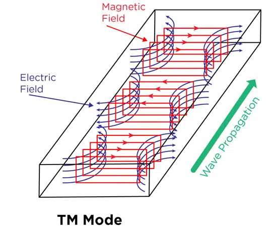
A TM mode solution involves the electric (E) field having components in the z-direction, which is along the direction of propagation, so that the magnetic (H) field is transverse, or at right angles to the z-direction (Figure 1).

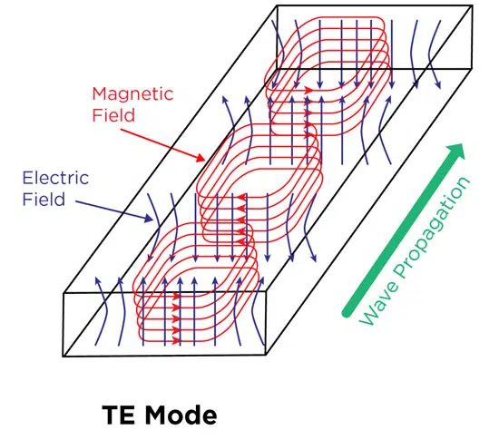
On the other hand, TE mode has E field components at right angles to the z-direction as shown in Figure 2.

Figure 1. The E and H fields for TM mode moving in a rectangular waveguide.
Figure 2. The E and H fields for TE mode moving in a rectangular waveguide.

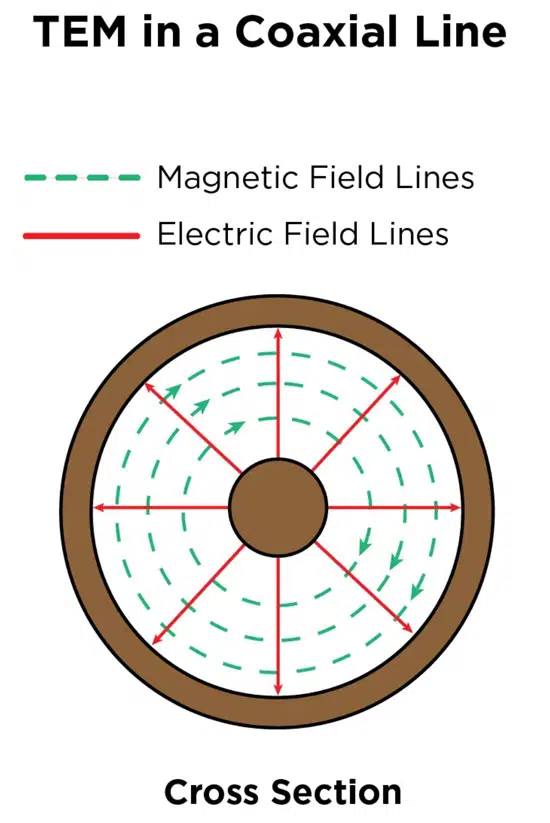
TEM mode has E field and H field components at right angles to the Z direction. Figure 3a shows an example of an electromagnetic wave propagating through space in TEM mode while Figure 3b shows how TEM mode works in a cross-section of a coax cable.

Figure 3a. Example of an electromagnetic wave propagating through space in TEM mode
Figure 3b. TEM mode in a cross-section of a coax cable

The Different Modes Supported by Transmission Lines and Waveguides

When we look at transmission lines and waveguides in terms of the electromagnetic modes supported, we can make clear distinctions between the two. A waveguide is a hollow tube made of a single conducting surface, which means it cannot support TEM mode.

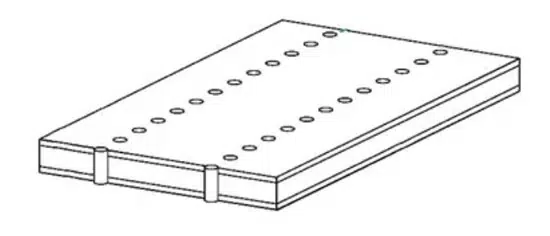
Figure 4. A representation of substrate-integrated waveguide SIW.

We usually see waveguides designed as a metal tube, but in recent years, the development of substrate-integrated waveguide (SIW) technology is changing this. An SIW is basically a rectangular waveguide in which the single conductor walls are formed by plated surfaces and vias. In this format, the wave uses TE mode to propagate in high dielectric-constant materials. A depiction of an SIW is shown in Figure 4.

Since a transmission line is a two-conductor structure, it can carry electromagnetic waves using TEM mode. A common example of a transmission line, although it is sort of going out of style now, is the coax cable shown in Figure 3b, which carries DOCSIS signals to cable TV boxes. Additional transmission line examples, the modes one would usually see, and their traditional performance characteristics compared to what you would see with a waveguide are all outlined in Table 1.
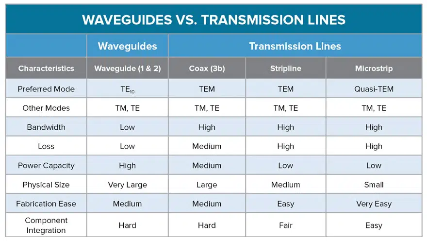
Table 1. With all other qualities of the application being equal, this Table provides an overview of how waveguides and different transmission line methods compare; source: Knowles Precision Devices

To summarize, the biggest thing to remember when it comes to waveguides versus transmission lines is that a waveguide = one conductor (usually a tube) and a transmission line = more than one conductor, such as the structure seen in a coax cable.

Related

Source: Knowles Precision Devices

Recent Posts

Modeling and Simulation of Leakage Inductance

9.5.2025
1

Murata and NIMS Built New Database of Dielectric Material Properties

5.5.2025
46

Shielding Cabinets

29.4.2025
17

Magnetic Shielding and Magnetic Shielding Sheets

29.4.2025
26

Corrosion its Development and Prevention

26.4.2025
25

Housing EMC Requirements, Issues and Solutions

26.4.2025
40

Hybrid Electrochemical Electrolytic Capacitor Provides High Frequency and High Capacitance Performance

25.4.2025
47

Non-Magnetic Interconnects

23.4.2025
13

RF Inductors Key Characteristics and Applications

17.4.2025
55

Kyocera Introducing SAW Filters for Implantable Medical and AED Applications

15.4.2025
28

Upcoming Events

May 14
11:00 - 12:00 CEST

Reliable RIGID.flex PCBs for Critical Applications – Made in Europe

May 14
17:00 - 17:30 CEST

Calculating Foil Winding Losses with AI

May 28
16:00 - 17:00 CEST

Power Over Data Line

View Calendar

Popular Posts

  • Buck Converter Design and Calculation

    0 shares
    Share 0 Tweet 0
  • Boost Converter Design and Calculation

    0 shares
    Share 0 Tweet 0
  • Flyback Converter Design and Calculation

    0 shares
    Share 0 Tweet 0
  • What is a Dielectric Constant and DF of Plastic Materials?

    4 shares
    Share 4 Tweet 0
  • Dual Active Bridge (DAB) Topology Explained

    0 shares
    Share 0 Tweet 0
  • Ripple Current and its Effects on the Performance of Capacitors

    3 shares
    Share 3 Tweet 0
  • Solid State Polymer Multilayer Capacitors For High Temperature Application

    0 shares
    Share 0 Tweet 0
  • LLC Resonant Converter Design and Calculation

    0 shares
    Share 0 Tweet 0
  • What is the Difference Between X8G, X8L and X8R Ceramic Capacitor Dielectrics?

    0 shares
    Share 0 Tweet 0
  • SEPIC Converter Design and Calculation

    0 shares
    Share 0 Tweet 0

Newsletter Subscription


Passive Components Blog

© EPCI - Leading Passive Components Educational and Information Site

  • Home
  • Privacy Policy
  • EPCI Membership & Advertisement
  • About

No Result
View All Result
  • Home
  • Knowledge Blog
  • Premium Suppliers

© EPCI - Leading Passive Components Educational and Information Site

This website uses cookies. By continuing to use this website you are giving consent to cookies being used. Visit our Privacy and Cookie Policy.
Go to mobile version