Passive Components Blog
No Result
View All Result
  • Home
  • NewsFilter
    • All
    • Aerospace & Defence
    • Antenna
    • Applications
    • Automotive
    • Capacitors
    • Circuit Protection Devices
    • electro-mechanical news
    • Filters
    • Fuses
    • Inductors
    • Industrial
    • Integrated Passives
    • inter-connect news
    • Market & Supply Chain
    • Market Insights
    • Medical
    • Modelling and Simulation
    • New Materials & Supply
    • New Technologies
    • Non-linear Passives
    • Oscillators
    • Passive Sensors News
    • Resistors
    • RF & Microwave
    • Telecommunication
    • Weekly Digest

    Samtec Expands Connector Severe Environment Testing Offering

    Silicon Capacitors Market: Shaping the Foundation for Next-Gen Miniaturization Electronics

    YAGEO Releases Compact Coupled Inductors for High-Density VR Designs

    Enhancing Energy Density in Nanocomposite Dielectric Capacitors

    Advances in the Environmental Performance of Polymer Capacitors

    Vishay Releases DLA Tantalum Polymer Capacitors for Military and Aerospace

    Vishay Expanded Inductor Portfolio With More Than 2000 Stock Items 

    Paumanok Releases Capacitor Foils Market Report 2025-2030

    Modelithics Welcomes CapV as a Sponsoring MVP

    Trending Tags

    • Ripple Current
    • RF
    • Leakage Current
    • Tantalum vs Ceramic
    • Snubber
    • Low ESR
    • Feedthrough
    • Derating
    • Dielectric Constant
    • New Products
    • Market Reports
  • VideoFilter
    • All
    • Antenna videos
    • Capacitor videos
    • Circuit Protection Video
    • Filter videos
    • Fuse videos
    • Inductor videos
    • Inter-Connect Video
    • Non-linear passives videos
    • Oscillator videos
    • Passive sensors videos
    • Resistor videos

    Connector PCB Design Challenges

    Efficient Power Converters: Duty Cycle vs Conduction Losses

    Ripple Steering in Coupled Inductors: SEPIC Case

    SEPIC Converter with Coupled and Uncoupled Inductors

    Coupled Inductors in SEPIC versus Flyback Converters

    Non-Linear MLCC Class II Capacitor Measurements Challenges

    Percolation Phenomenon and Reliability of Molded Power Inductors in DC/DC converters

    Root Causes and Effects of DC Bias and AC in Ceramic Capacitors

    How to Calculate the Output Capacitor for a Switching Power Supply

    Trending Tags

    • Capacitors explained
    • Inductors explained
    • Resistors explained
    • Filters explained
    • Application Video Guidelines
    • EMC
    • New Products
    • Ripple Current
    • Simulation
    • Tantalum vs Ceramic
  • Knowledge Blog
  • Suppliers
    • Who is Who
  • Events
No Result
View All Result
Passive Components Blog
No Result
View All Result

A Guide to Understanding Common Mode Choke

18.12.2024
Reading Time: 4 mins read
A A

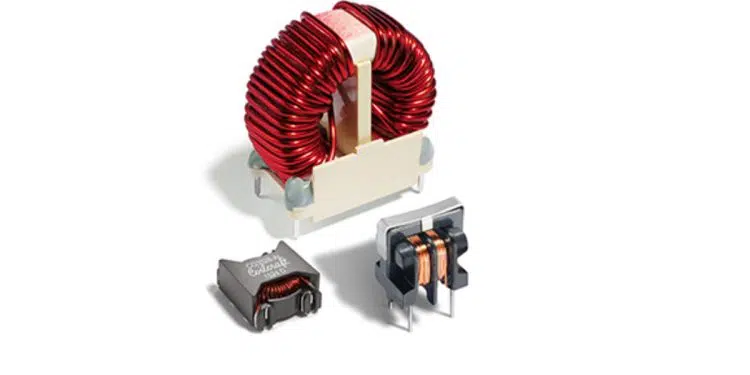
This article written by Chris Hare, Coilcraft provides a guide to understanding of common mode choke.

What is a Common Mode Choke?

RelatedPosts

Coilcraft Introduces LLC Half-Bridge Transformers for High-Frequency Applications

Coilcraft Unveils 165C High-Temperature Coupled Inductors

Coilcraft Extends Air Core RF Inductors

A common mode choke is an electrical filter that blocks high frequency noise common to two or more data or power lines while allowing the desired DC or low-frequency signal to pass.

Common mode (CM) noise current is typically radiated from sources such as unwanted radio signals, unshielded electronics, inverters and motors. Left unfiltered, this noise presents interference problems in electronics and electrical circuits.

How do Common Mode Chokes Work?

In normal or differential mode (single choke), current travels on one line in one direction from the source to the load, and in the opposite direction on the return line that completes the circuit.

In common mode, the noise current travels on both lines in the same direction.

common mode choke vs differential mode choke current flow

Common mode chokes have the two or more windings arranged such that the common mode current creates a magnetic field that opposes any increase in common mode current. This is similar to how single line (differential) inductors function. Inductors create magnetic fields that oppose changes in current.

In common mode, the current in a group of lines travels in the same direction so the combined magnetic flux adds to create an opposing field to block the noise, as illustrated by the red and green arrows in the toroid core shown in Figure 1. In differential mode, the current travels in opposite directions and the flux subtracts or cancels out so that the field does not oppose the normal mode signal.

How do I Choose a Common Mode Choke?

The main criteria for selecting a common mode choke are:

  • Required impedance: How much attenuation of noise is needed?
  • Required frequency range: Over what frequency bandwidth is the noise?
  • Required current-handling: How much differential mode current must it handle?

High-Speed and Super-Speed Data Line EMI Chokes

USB, high-speed and Super-Speed data line common mode chokes effectively reduce common mode noise in high-speed interfaces like USB 2.0, USB 3.1 Gen 1, HDMI, IEEE 1394, LVDS, HDBaseTTM, MOST® bus, etc. They maintain excellent signal integrity for high-speed communications with -3 dB differential mode cutoff frequencies up to 6.5 GHz. Most provide greater than 30 dB common mode attenuation at 500 MHz and 25 dB in the GHz band.

Data Line Common Mode EMI Chokes

Surface mount data line common mode chokes are designed to attenuate common mode noise up to 100 MHz. The PDLF Series can reduce noise by a factor of 32 from 15 MHz to 300 MHz and are available in 2, 3 and 4 line versions. The PTRF Series is optimized for FCC and ITU-T (formerly CCITT) requirements. These parts provide 15 to 25 dB attenuation, greater than 1000 Ohms impedance and 1500 V isolation between windings. M2022 can suppress common mode noise up to 500 MHz in a compact 1812 package.

Data/Power Line Common Mode EMI Chokes

LPD, MSD and PFD Families are low profile, miniature footprint common mode chokes that can be used to attenuate common mode noise or differential mode noise in both data and power line applications.

Surface Mount Power Line Common Mode EMI Chokes

Low-cost, high performance surface mount power line common mode chokes come in a variety of sizes and packages. They are designed to eliminate AC line-conducted common mode noise across a broad range of frequencies, with up to 1500 Vrms isolation. These common mode chokes can operate over a wide range of current from 0.06 Amps to 15 Amps, providing attenuation where line filtering is needed, such as in switch-mode power supplies.

Through-Hole Power Line Common Mode EMI Chokes

Low-cost through-hole BU Series high efficiency choke coils are designed to eliminate line conducted common mode noise across a broad range of frequencies. The BU9S and BU9HS are ideal for signal line applications; the other BUs can be used in switching power supplies and power supply circuits. For low profile applications, the BU9 and BU9S filters are available in a horizontal configuration that reduces their height to under half an inch (12.5 mm).

CMT Common Mode EMI Chokes

CMT toroid style common mode chokes are designed to provide the highest common mode impedance over the widest frequency range. These parts are ideal for any application requiring a high DC current bias and are well suited for use in switch-mode power supplies. These common mode chokes are most effective in filtering supply and return conductors with in-phase signals of equal amplitude. Differential mode inductors are available for filtering out-ofphase or uneven amplitude signals.

Related

Source: Coilcraft

Recent Posts

Silicon Capacitors Market: Shaping the Foundation for Next-Gen Miniaturization Electronics

10.10.2025
6

YAGEO Releases Compact Coupled Inductors for High-Density VR Designs

9.10.2025
12

Enhancing Energy Density in Nanocomposite Dielectric Capacitors

9.10.2025
14

Advances in the Environmental Performance of Polymer Capacitors

8.10.2025
31

Vishay Expanded Inductor Portfolio With More Than 2000 Stock Items 

8.10.2025
11

Benefits of Tantalum Powder Stress–Strain Curve Evaluation vs Conventional Wet Test

3.10.2025
23

Electrolyte Selection and Performance in Supercapacitors

3.10.2025
31

Connector PCB Design Challenges

3.10.2025
34

Researchers Demonstrated High Energy Ceramic Capacitors Stable in Wide Temperature Range

2.10.2025
24

How to Manage Supercapacitors Leakage Current and Self Discharge 

1.10.2025
44

Upcoming Events

Oct 14
16:00 - 17:00 CEST

Smart Sensors, Smarter AI: Building Reliable Edge Systems

Oct 17
12:00 - 14:00 EDT

External Visual Inspection per MIL-STD-883 TM 2009

Oct 20
October 20 - October 23

Digital WE Days 2025 – Virtual Conference

Oct 21
October 21 @ 12:00 - October 23 @ 14:15 EDT

Space and Military Standards for Hybrids and RF Microwave Modules

Oct 28
8:00 - 15:00 CET

Power Up Your Design: SN6507 and the Ready-to-Use Development Kit

View Calendar

Popular Posts

  • Buck Converter Design and Calculation

    0 shares
    Share 0 Tweet 0
  • Boost Converter Design and Calculation

    0 shares
    Share 0 Tweet 0
  • Flyback Converter Design and Calculation

    0 shares
    Share 0 Tweet 0
  • LLC Resonant Converter Design and Calculation

    0 shares
    Share 0 Tweet 0
  • What is a Dielectric Constant and DF of Plastic Materials?

    4 shares
    Share 4 Tweet 0
  • SEPIC Converter Design and Calculation

    0 shares
    Share 0 Tweet 0
  • Dual Active Bridge (DAB) Topology Explained

    0 shares
    Share 0 Tweet 0
  • Ripple Current and its Effects on the Performance of Capacitors

    3 shares
    Share 3 Tweet 0
  • MLCC and Ceramic Capacitors

    0 shares
    Share 0 Tweet 0
  • Flying Capacitors Explained

    0 shares
    Share 0 Tweet 0

Newsletter Subscription


Passive Components Blog

© EPCI - Leading Passive Components Educational and Information Site

  • Home
  • Privacy Policy
  • EPCI Membership & Advertisement
  • About

No Result
View All Result
  • Home
  • Knowledge Blog
  • Premium Suppliers

© EPCI - Leading Passive Components Educational and Information Site

This website uses cookies. By continuing to use this website you are giving consent to cookies being used. Visit our Privacy and Cookie Policy.
Go to mobile version