Passive Components Blog
No Result
View All Result
  • Home
  • NewsFilter
    • All
    • Aerospace & Defence
    • Antenna
    • Applications
    • Automotive
    • Capacitors
    • Circuit Protection Devices
    • electro-mechanical news
    • Filters
    • Fuses
    • Inductors
    • Industrial
    • Integrated Passives
    • inter-connect news
    • Market & Supply Chain
    • Market Insights
    • Medical
    • Modelling and Simulation
    • New Materials & Supply
    • New Technologies
    • Non-linear Passives
    • Oscillators
    • Passive Sensors News
    • Resistors
    • RF & Microwave
    • Telecommunication
    • Weekly Digest

    Exxelia Miniaturized 400 MHz Invertedโ€‘F Antenna

    Wรผrth Elektronik Unveils High-Current Automotive Power Inductor

    Transformer-Based Power-Line Harvester Magnetic Design

    Tantalum Capacitor Anode Manufacturing Quality Management

    Middle East Conflict: The Potential Impact to Passive Components

    Wk 12 Electronics Supply Chain Digest

    Designing a 2 kW LLC Transformer with Integrated Resonant Inductor

    Inductor Technology Dossier

    Coilcraft Releases TLVR Inductors for High Density VRMs and PoL Converters

    Trending Tags

    • Ripple Current
    • RF
    • Leakage Current
    • Tantalum vs Ceramic
    • Snubber
    • Low ESR
    • Feedthrough
    • Derating
    • Dielectric Constant
    • New Products
    • Market Reports
  • VideoFilter
    • All
    • Antenna videos
    • Capacitor videos
    • Circuit Protection Video
    • Filter videos
    • Fuse videos
    • Inductor videos
    • Inter-Connect Video
    • Non-linear passives videos
    • Oscillator videos
    • Passive sensors videos
    • Resistor videos

    Transformer-Based Power-Line Harvester Magnetic Design

    Thermal Modeling of Magnetics

    Standard vs Planar LLC transformers Comparison for Battery Chargers

    How Modern Tools Model Magnetic Components for Power Electronics

    Advanced Loss Modeling for Planar Magnetics in the Frenetic Planar Tool

    2026 Power Magnetics Design Trends: Flyback, DAB and Planar

    Enabling Softwareโ€‘Defined Vehicle Architectures: Automotive Ethernet and Zonal Smart Power

    Calculating Resistance Value of a Flyback RC Snubberย 

    Oneโ€‘Pulse Characterization of Nonlinear Power Inductors

    Trending Tags

    • Capacitors explained
    • Inductors explained
    • Resistors explained
    • Filters explained
    • Application Video Guidelines
    • EMC
    • New Products
    • Ripple Current
    • Simulation
    • Tantalum vs Ceramic
  • Knowledge Blog
  • DossiersNew
  • Suppliers
    • Who is Who
  • PCNS
    • PCNS 2025
    • PCNS 2023
    • PCNS 2021
    • PCNS 2019
    • PCNS 2017
  • Events
No Result
View All Result
Passive Components Blog
No Result
View All Result

ADL New Plug & Play Solution for Supercapacitor Balancing

1.4.2020
Reading Time: 114 mins read
A A

Source: ALD Analogue Linear Devicesย article

By Paul Pickering, ALD

RelatedPosts

Exxelia Miniaturized 400 MHz Invertedโ€‘F Antenna

Wรผrth Elektronik Unveils High-Current Automotive Power Inductor

Transformer-Based Power-Line Harvester Magnetic Design

Supercapacitors are unique because they can work in conjunction with or as an alternative to batteries in applications needing many rapid charge/discharge cycles and are popular in applications such as short-term energy storage, regenerative braking, and static RAM memory backup.ย But balancing a supercapacitor in a design involves more than connecting a few wires. When a supercapacitor has an operating voltage of 2.5V โ€“ 2.7V, most applications use an array of devices connected in series for higher voltage.

Many supercapacitors have a leakage current which varies based on numerous factors, including:

  • Initial leakage value
  • Leakage variation with charging voltage, charging current and temperature
  • Operating temperature range
  • Chemistry, Material, and Construction
  • Aging

In a cell, differences in leakage currents between individual supercapacitors result in changes in voltages across them over time; this can cause reduced lifespan and eventual failure since exceeding the maximum voltage on a supercapacitor can lead to cell failure.

Preventing this imbalance requires a balancing circuit that keeps the voltage across each supercapacitor within limits by automatically correcting the effects of changing leakage currents, all with minimal added leakage current or power consumption.

For the module designer, this represents an additional layer of complexity. A simple resistor-based design dissipates power and doesnโ€™t respond to aging and temperature variations; an opamp-based design has higher performance, but is complicated, also wastes power and consumes excessive board space. Developing a solution also requires layout expertise and analog or power design skills; the result may be added development time or even make the problem worse and add unwanted leakage of its own.

Overview of a new Printed Circuit Board

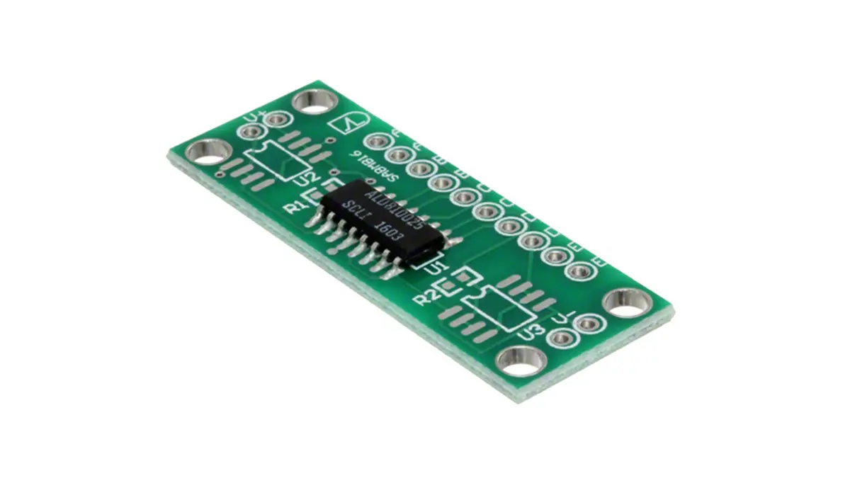
A new printed circuit board (PCB) offers a โ€œplug and play solutionโ€ by combining all of the circuitry required to accomplish these tasks for any size supercaps. Figure 1 shows the board, which is designed to be used in conjunction with precision MOSFET arrays.

Each board measures only 0.6โ€ x 1.6โ€ and when fully populated can balance up to four supercapacitors connected in series; in addition to the unpopulated, populated boards

are available with different combinations of MOSFETS to reach required voltages. For larger arrays, any number of boards can be connected in series, subject only to a maximum voltage per board of 15V.

page2image2507969088

Figure 1 left: four supercapacitors plus external components courtesy of Advanced Linear Devices (ALD).

The board can accommodate supercapacitors from 0.1F to 3000F and beyond. The average additional power dissipation due to the use of the boards is zero, which makes this method of supercapacitor balancing very energy-efficient. It is especially suited for low loss energy harvesting and long life battery-operated applications.

Figure 2 shows the schematic of the board used with four supercapacitors C1 โ€“ C4.ย The MOSFET is an array of four identical chips; that contains two devices in an identical configuration. Depending on the board selected, each supercapacitor can have a single MOSFET, or two devices in parallel, connected across it. Connecting two devices inย parallel gives an equivalent MOSFET with twice the output current and twice the sensitivity to voltage change.

The โ€œXXโ€ in both part numbers denotes the voltage across the MOSFET that corresponds to a leakage current of 1uA at 25ยฐC, as discussed in the next section.

Each MOSFET is rated for a reverse bias diode current of up to 80 mA maximum. Any reverse bias condition as a result of changing supercapacitor voltages, especially during fast supercapacitor discharge, could lead to some internal nodes becoming reverse biased with surge current in excess of this limit.

The board has TO277 pads for adding external Schottky rectifiers (power diodes) to clamp such current transients.

An optional resistor can also be connected across each pair of supercapacitors. Normally this is left open, but if those two supercapacitor locations are unpopulated a zero-ohm jumper in the corresponding location should be installed.

page3image2588522672

Figure 2: schematic of a fully-populated board with three MOSFET arrays. The design ensures that the voltage across each supercap (VA โ€“ VB, for example) does not exceed the maximum allowed value. Courtesy of Advanced Linear Devices

Circuit Operation

How does the circuit automatically balance leakage? A MOSFET can be considered as a three-terminal voltage-controlled resistor over a limited operating range, with the โ€œonโ€ resistance RDS(ON) an exponential function of the input voltage VGS. When the gate and drain are connected, VDS is also equal to VGS, and called the threshold voltage Vt. Figure 3 shows the data for the quad MOSFET array.

page5image2506177504

Figure 3: The chip relative ON resistance vs. input voltage courtesy of ALD .

The โ€œXXโ€ in the ALD part numbers denotes the threshold voltage Vt that gives an output current IOUT of 1ฮผA at 25ยฐC. For example, the ALD810025 quad array has Vt = 2.5V, so IOUT = 1ฮผA at 2.5V and 25ยฐC. This corresponds to an RDS(ON) of 2.5Mฮฉ. Table 1 shows the change in IOUT as Vt varies.

Output Current

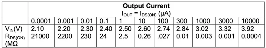
Table 1: Equivalent ON resistance at different input voltages and output currents for the ALD810025 at TA = 25ยฐC.

When a MOSFET is connected across a supercapacitor in an array, the exponential relationship between Vt and RDS(ON) means that any small increase in the supercapacitor voltage caused by leakage current from another supercapacitor will cause a large decrease in the RDS(ON) of that MOSFET. This will increase IDS(ON) and reduce the voltage. As the voltage decreases, IDS(ON) will also decrease.

Depending on the PCB part number selected, each supercapacitor can have a single MOSFET or two devices in parallel connected across it. Connecting two devices in parallel gives an equivalent MOSFET with twice the output current and twice the sensitivity to voltage change.

The leakage current balancing mechanism is fully automatic and works for supercapacitor arrays with different leakage current profiles. In a stack with many supercapacitors in series, multiple MOSFET arrays function to balance the various leakage currents.

For example, if leakage current IC1 is greater than IC2 in the four-capacitor array in figure 2, then both M1s (in U1 and U2) are turned off and the M2 pair becomes the active circuit element to balance C1, the supercapacitor with the greatest leakage.

Without the auto-balancing circuit, the voltage across C2 can keep rising until it destroys the part. The MOSFET balancing solution contributes virtually no additional current drain and adjusts for temperature, time, and other environmental changes that may contribute to out-of-balance conditions.

When an MOSFET is connected across a supercapacitor in an array, any increase in the supercapacitor voltage caused by leakage current from another supercap will cause a decrease in the RDS(ON) of that MOSFET. This will increase IDS(ON) and reduce the voltage. As the voltage decreases, IDS(ON) will also decrease. The leakage current balancing is fully automatic and works for a variety of supercapacitors, each with a different leakage current characteristic profile.

The MOSFET balancing solution contributes virtually no additional current drain and adjusts for temperature, time, and other environmental changes that may contribute to out-of-balance conditions. In a stack with many supercapacitors in series, multiple SAB MOSFET arrays function to balance the various leakage currents. For example, if leakage current IC1 is greater than IC2 in the four-capacitor array in figure 2, then both M1s (in U1 and U2) are turned off and the M2 pair becomes the active circuit element to balance C1, the supercapacitor with the greatest leakage.

Without the auto-balancing circuit, the voltage across C2 (VB – VC) can keep rising until it destroys C2 with overvoltage.

By providing a plug-and-play solution to the problem of balancing leakage currents in supercapacitors, the new PCB saves both time and effort for designers who must integrate them into their modules.

Related

Recent Posts

Transformer-Based Power-Line Harvester Magnetic Design

24.3.2026
4

Tantalum Capacitor Anode Manufacturing Quality Management

23.3.2026
14

Middle East Conflict: The Potential Impact to Passive Components

23.3.2026
72

Designing a 2 kW LLC Transformer with Integrated Resonant Inductor

20.3.2026
44

Murata to Decouple China Rare Earth Supply in 3 Years

19.3.2026
156
Schematic illustration of the electric double layer of porous carbon electrodes at elevated potentials in a a conventional electrolyte and b a weakly solvating electrolyte; source: authors

Researchers Presented Lignin-based Electrolyte for 4V Supercapacitors with Low Selfโ€‘Discharge

19.3.2026
25

Samsung Outlines Growth Roadmap at its 52nd General Shareholders Meeting

19.3.2026
23

Samsung Electro-Mechanics Enters LEO Satellite Market With Highโ€‘Reliability MLCCs

19.3.2026
35

Exxelia to Exhibit at APEC 2026 in San Antonio, Texas

17.3.2026
35

Upcoming Events

Apr 21
16:00 - 17:00 CEST

Heatsink Solutions: Thermal Management in electronic devices

May 5
16:00 - 17:00 CEST

Understanding and Selecting Capacitors – Fundamentals, Technologies and Latest Trends

May 19
16:00 - 17:00 CEST

Designing Qi2 Wireless Power Systems: Practical Development and EMC Optimization

View Calendar

Popular Posts

  • Buck Converter Design and Calculation

    0 shares
    Share 0 Tweet 0
  • Boost Converter Design and Calculation

    0 shares
    Share 0 Tweet 0
  • Flyback Converter Design and Calculation

    0 shares
    Share 0 Tweet 0
  • LLC Resonant Converter Design and Calculation

    0 shares
    Share 0 Tweet 0
  • MLCC and Ceramic Capacitors

    0 shares
    Share 0 Tweet 0
  • Dual Active Bridge (DAB) Topology

    0 shares
    Share 0 Tweet 0
  • MLCC Manufacturers Consider Price Increase as AI Demand Outpaces Supply

    0 shares
    Share 0 Tweet 0
  • Ripple Current and its Effects on the Performance of Capacitors

    3 shares
    Share 3 Tweet 0
  • MLCC Case Sizes Standards Explained

    0 shares
    Share 0 Tweet 0
  • What is a Dielectric Constant and DF of Plastic Materials?

    4 shares
    Share 4 Tweet 0

Newsletter Subscription


Passive Components Blog

ยฉ EPCI - Leading Passive Components Educational and Information Site

  • Home
  • Privacy Policy
  • EPCI Membership & Advertisement
  • About

No Result
View All Result
  • Home
  • Knowledge Blog
  • PCNS

ยฉ EPCI - Leading Passive Components Educational and Information Site

This website uses cookies. By continuing to use this website you are giving consent to cookies being used. Visit our Privacy and Cookie Policy.
Go to mobile version