


This technical blog article written by Ron Demcko and Slavomir Pala, KYOCERA-AVX Components Corporation, explains use of aluminum electrolytic capacitors in three-phase BLDC motor controllers.
The uses of industrial control systems and robotics are expanding rapidly due to their positive impact on costs and quality. This paper will discuss Aluminum Electrolytic capacitor roles as an output filter capacitor to improve power quality in Brushless DC Motor (BLDC) motor controller & drives.
Aluminum Electrolytic capacitors can be used to provide exacting drive voltage to motors. This in turn improves system reliability and performance. The case studied will be a 3-phase, 24V / 30 watt BLDC motor with a rated speed of 4000rpm and rated torque of 0.072 N-m.
Introduction
Both motors & actuators convert control signals into physical motion. Motors and actuators are of no use without being able to instruct their movement. Control of motors & actuators is commonly accomplished by low level ICs. Those ICs could be a simple Micro-controller, Microprocessor or FPGA – but regardless of the specific device, these ICs do not have sufficient output voltage to directly drive a motor. Thus the need for an interface between the control silicon and the motor load motor. Enter the motor controller.
A motor controller is a device that allows low level logic silicon control a motor. It essentially acts as an intermediate device between the silicon and the motors power source and the motor. Some motor controllers have enough processing power on board that they can control a motor directly. Hand adjusted variable speed motor drivers are a possible example of a motor controller having ample processing power on board. More complex feedback and control scenarios may require added processing power and potentially a data bus from control logic to a motor driver.
Motor controllers vary greatly depending upon the motor type, power level/size, level of control needed and a variety of other factors. Regardless of their exact configuration, motor controllers are an essential part of industrial controllers and robotics. The purpose of this investigation is to show the impact of properly sized Aluminum Electrolytic capacitors on the voltage drive lines to a common 3-phase motor used in robotics or industrial automation.
Motor types vary greatly and this study was based upon Brushless DC Motors (BLDC). These motors are available in single-phase, two-phase and three-phase configurations. The 3-phase type is most commonly used and therefore the specific type investigated in this study.
BLDCs are used across a wide range of industries such as transportation, aerospace, appliances, consumer, instrumentation and industrial automation. Many times the voltage rating of the BLDC hints to its end use. BLDCs that are less than or equal to 48V are commonly used in automotive, robotics, small arm assists etc. In comparison, BLDCs that are >100V are commonly used in appliances and industrial automation.
At first glance, the most noted feature of BLDCs over other motor types is that BLDCs exhibit a higher ratio of torque relative to the motor size. This reduces the size of motor needed in many applications and makes BLDCs exceptionally useful in applications where volume and weight are at a premium.
However, BLDCs offer another major advantage – electrical efficiency. A BLDC can reduce energy consumption by 20 to 30 percent vs. traditional brushed motors given similar run & load conditions [1]. This is very significant and translates into an increase of 20 to 30 percent in run time assuming similar sized batteries. Alternatively – the battery for an end use BLDC can be 20 to 30% smaller thus making smaller, lighter products. The feature is particularly important in drones, hand held tools and robotics. Additional features guiding designers to BLDC and a comparison to brushed DC motors are shown in
Figure 1 [1]:

BLDC motors do not use brushes for commutation but instead utilize electronics to create a commutation function. Basically, the motor controller will create an electronically generated varying magnetic field by changing voltages and currents injected to the various phases of the motor. Therefore a potential disadvantage of BLDCs is the added cost and complexity of motor controllers. However, costs of motor controllers are dropping based upon either:
- Traditional & expected semiconductor cost reduction through efficiency optimization & volume growth
- The integration of adequate power MCUs with potentially internal metal-oxide semiconductor field-effect transistors (MOSFETs). More powerful semiconductors
can essentially act as a cost reduced System on Chip.
Numerous suppliers have created a wide array of motor controllers that are low cost & easy to implement. Modern motor controllers perform multiple functions of [2]:
- Regulates motor speed, torque, or power output
- Controls startup or soft starts
- Protects against circuit faults
- Smooths motor acceleration and deceleration
- Protects against overloads
To summarize, advances in semiconductor technology have delivered easy to use, powerful, cost effective motor controllers.
Test Platform
A major consideration for our testing a motor controller was to find one thats affordable, has high levels of reliability and supports a wide range of applications. An Allegro A4915 was chosen based upon our selection criteria. The A4915 is a cost effective 3 phase BLDC motor driver that eliminates the need for a control microprocessor. The devices voltage rating and drive capability supports a wide range of motor loads with 5V minimum voltage & also offers an integrated sleep function. These features make it ideal for battery operated applications. The A4915 is suited for a variety of loads with gate
drive voltages rated to 50 volts and supports to load currents up to 150 amps.

The A4915 has internal synchronous rectification control circuitry. It is provided to improve power dissipation in the external MOSFETs during PWM operation. Internal circuit protection includes latched thermal shutdown, dead time protection, and undervoltage lockout. Special power up sequencing is not required. The A4915 is supplied in a 28-pin TSSOP with an exposed thermal pad (suffix LP) and a 28-contact 5 × 5 mm QFN with an exposed thermal pad. [3]
The A4915 can be pulse width modulated (PWM) to control current. There are two methods by which PWM can be applied to the device:
- External PWM.
- Internal PWM – Speed controlled by applying a DC voltage to SPEED pin.
Our testing utilized the internal PWM method. The motor chosen was an Applied Motion Products 3 phase BLDC with 24V DC voltage rating and rated Torque of 0.072 N-M. The motors small size, light weight (0.32 kg) and speed 4000 RPM rated with 5000 RPM maximum makes it an ideal candidate for a variety of portable applications.
Test Results and Discussions
Aluminum electrolytic capacitors are intended for applications where large capacitance values are required in relatively small, light packages. Tantalum capacitors technically offer a higher capacitance density but aluminum electrolytics meet the cost targets for general bulk capacitors required by all but the most miniature/micro sized BLDC motor drives.
Tests were conducted to illustrate the impact of the Aluminum electrolytic output capacitors effect under identical motor load conditions. In this test PWM output waveforms were captured at similar output driving ports.
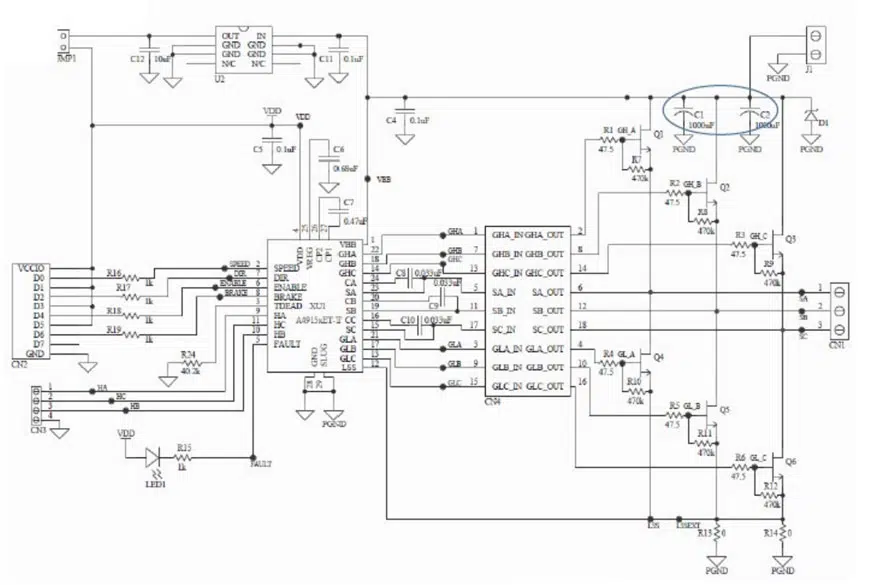
Three output capacitor scenarios were evaluated for capacitors C1 and C2. The location of C1 and C2 can be found in the circled region of Figure 2. This schematic is an excerpt from documentation on the Allegro 4915 evaluation board [3]. The test cases were:
- Case 1 – No capacitors populated at C1 and C2
- Case 2 – C1 and C2 both 1000µF 50V Radial Electrolytic Capacitors
- Case 3 – C1 and C2 both 1500µF 80V Radial Electrolytic Capacitors
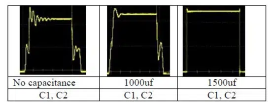
Similar motor loading, RPM and run time was used in comparing the drive waveform integrity. As expected, the elimination of capacitors C1 and C2 effect the output waveform with the introduction of measurable ringing (approximately 8 volts). Such ringing could reduce the drive control response and integrity of the motor.
The introduction of two 1000µF capacitors placed at C1 and C2 reduced the ringing greatly to approximately 4 volts. Finally, the replacement of C1 and C2 by 1500µF Aluminum Electrolytic resulted in a ringing of ~ 0.5 volts. A summary of these test results are shown in Figure 3 – Output waveform quality vs bulk capacitor value.
Output capacitors value play a crucial role in the integrity of motor controllers. Specific capacitance values which are optimal for designs vary greatly since motor controllers come in various configurations and power levels intended to address the wide range of BLDCs and end applications.
Regardless of the exact value & capacitor configuration, aluminum electrolytic capacitors are ideal in these types of wide voltage range, low frequency pulsed applications. The capacitor should be sized such that surges do not exceed the rated DC voltage of the capacitor. As a general rule of thumb – aluminum electrolytic applications should be tolerant to excess capacitance values over the nominal value and in the case of polarized aluminum electrolytic capacitors – no reverse voltage should be applied.
The vast majority of motor controllers utilize Aluminum Electrolytic technology for output capacitors because of the above characteristics.
Summary and Conclusions
Brushless DC motors are experiencing widespread growth in across virtually all applications sectors. BLDCs are attractive to end users due to size efficiency and weight advantages over traditional brushed DC motors. Though motor controllers are needed for BLDC control – design costs and complexity can be kept to a minimum through a wide range of controllers available for virtually every type of BLDC and power level application. Further controller cost effectiveness is expected from accelerating advances in semiconductors used within BLDC controllers.
Output capacitors value play a crucial role in the integrity of motor controllers. Specific capacitance values which are optimal for designs vary greatly since motor controllers come in various configurations and power levels intended to address the wide range of BLDCs and end applications. Aluminum electrolytic
capacitors are ideal for use in motor controllers due to their small size, light weight and attractive capacitance value range.
References
[1] MicroChip; AN885 – Brushless DC (BLDC) Motor Fundamentals, Padmaraja Yedamale, 2003; https://ww1.microchip.com/downloads/en/appnotes/00885a.pdf
[2] David Schnaufer et all; Qorvo – Motor Control Fundamentals, ISBN 978-1-119-68172-4, John Wiley & Sons 2020
[3] Allegro Microsystems; A4915 3-Phase MOSFET Driver data sheet; https://www.allegromicro.com/en/products/motor-drivers/bldc-drivers/a4915


