Passive Components Blog
No Result
View All Result
  • Home
  • NewsFilter
    • All
    • Aerospace & Defence
    • Antenna
    • Applications
    • Automotive
    • Capacitors
    • Circuit Protection Devices
    • electro-mechanical news
    • Filters
    • Fuses
    • Inductors
    • Industrial
    • Integrated Passives
    • inter-connect news
    • Market & Supply Chain
    • Market Insights
    • Medical
    • Modelling and Simulation
    • New Materials & Supply
    • New Technologies
    • Non-linear Passives
    • Oscillators
    • Passive Sensors News
    • Resistors
    • RF & Microwave
    • Telecommunication
    • Weekly Digest

    Wk 40 Electronics Supply Chain Digest

    Benefits of Tantalum Powder Stress–Strain Curve Evaluation vs Conventional Wet Test

    Electrolyte Selection and Performance in Supercapacitors

    Connector PCB Design Challenges

    Researchers Demonstrated High Energy Ceramic Capacitors Stable in Wide Temperature Range

    Stackpole Offers High Voltage Plate Resistors up to 40KV

    How to Manage Supercapacitors Leakage Current and Self Discharge 

    Qualification of Commercial Supercapacitors for Space Applications

    Experimental Evaluation of Wear Failures in SMD Inductors

    Trending Tags

    • Ripple Current
    • RF
    • Leakage Current
    • Tantalum vs Ceramic
    • Snubber
    • Low ESR
    • Feedthrough
    • Derating
    • Dielectric Constant
    • New Products
    • Market Reports
  • VideoFilter
    • All
    • Antenna videos
    • Capacitor videos
    • Circuit Protection Video
    • Filter videos
    • Fuse videos
    • Inductor videos
    • Inter-Connect Video
    • Non-linear passives videos
    • Oscillator videos
    • Passive sensors videos
    • Resistor videos

    Connector PCB Design Challenges

    Efficient Power Converters: Duty Cycle vs Conduction Losses

    Ripple Steering in Coupled Inductors: SEPIC Case

    SEPIC Converter with Coupled and Uncoupled Inductors

    Coupled Inductors in SEPIC versus Flyback Converters

    Non-Linear MLCC Class II Capacitor Measurements Challenges

    Percolation Phenomenon and Reliability of Molded Power Inductors in DC/DC converters

    Root Causes and Effects of DC Bias and AC in Ceramic Capacitors

    How to Calculate the Output Capacitor for a Switching Power Supply

    Trending Tags

    • Capacitors explained
    • Inductors explained
    • Resistors explained
    • Filters explained
    • Application Video Guidelines
    • EMC
    • New Products
    • Ripple Current
    • Simulation
    • Tantalum vs Ceramic
  • Knowledge Blog
  • Suppliers
    • Who is Who
  • Events
No Result
View All Result
Passive Components Blog
No Result
View All Result

Antenna Matching on PCB

11.8.2025
Reading Time: 2 mins read
A A

In this video from Würth Elektronik you will learn about antenna matching with PCB board.

Developing a Smart Product with Optimal Antenna Matching

RelatedPosts

Connector PCB Design Challenges

Different Causes of Capacitor Degradation and Failure Mechanisms

Würth Elektronik Announces 2025 Digital WE Days Virtual Conference

In the development of smart products utilizing Wi-Fi modules, the integration of a multi-layer chip antenna on the board is crucial. Initial attempts to solder an antenna onto a standard demo board revealed the need for expert guidance to achieve proper antenna matching.

Understanding Antenna Matching

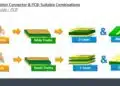
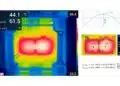
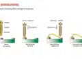
Antenna matching is a critical process that ensures optimal signal transmission and reception. The diagram below illustrates a typical PCB layout, featuring a return plate or antenna, a signal line, and a matching circuit. It is important to note that this antenna design does not require a ground plane beneath it. The current matching for the 2.4 GHz frequency is suboptimal, as observed. To address this, a capacitor was added to the signal line, resulting in improved matching. However, this solution is not suitable for Wi-Fi applications, as it only covers a broader frequency range.

The Role of a Matching Circuit

A matching circuit generally consists of two or three components. While a single capacitor can provide a matching circuit for various frequencies, our focus must be on the specific 2.4 GHz range. Incorporating inductance into the circuit offers a more effective solution.

A Promising Solution

The integration of inductance has led to significant improvements. The performance now spans from 2.4 to 2.5 GHz, with excellent session loss, indicating a 100 MHz bandwidth. This ensures that nearly the entire signal passes through the antenna, with only 15% signal loss, which is acceptable. However, it is anticipated that integrating this solution into the actual board may yield different results. Rematching will be necessary not only with the board but also with the enclosure, as environmental factors can influence performance. To mitigate this, a non-metallic enclosure is recommended.

This development not only benefits individual projects but also presents an opportunity to offer antenna matching services to customers. Our antenna matching team is available to assist with product development, ensuring optimal performance across various environments.

Related

Source: Würth Elektronik

Recent Posts

Connector PCB Design Challenges

3.10.2025
16

What Track Width To Use When Routing PCB

6.6.2025
66

IPC Class 2 vs Class 3 Solder Joints Requirements Explained

27.2.2025
559

How to Determine Chip Temperature

3.1.2025
243

Die and Wire PCB Bonding Explained

1.7.2025
164

EMI Shielding Challenges

1.7.2025
16

EMC with Electromechanical Inter-Connections

1.7.2025
18

Designing and Testing HDI PCBs for Harsh Environments

1.7.2025
11

RF PCB Connector Impedance Matching and Dynamics

1.7.2025
80

Basic PCB Technology Overview

1.7.2025
23

Upcoming Events

Oct 8
11:00 - 12:00 CEST

PCB Online Shop – simply “Made in Germany” by Würth Elektronik

Oct 14
16:00 - 17:00 CEST

Smart Sensors, Smarter AI: Building Reliable Edge Systems

Oct 17
12:00 - 14:00 EDT

External Visual Inspection per MIL-STD-883 TM 2009

Oct 20
October 20 - October 23

Digital WE Days 2025 – Virtual Conference

Oct 21
October 21 @ 12:00 - October 23 @ 14:15 EDT

Space and Military Standards for Hybrids and RF Microwave Modules

View Calendar

Popular Posts

  • Buck Converter Design and Calculation

    0 shares
    Share 0 Tweet 0
  • Boost Converter Design and Calculation

    0 shares
    Share 0 Tweet 0
  • Flyback Converter Design and Calculation

    0 shares
    Share 0 Tweet 0
  • LLC Resonant Converter Design and Calculation

    0 shares
    Share 0 Tweet 0
  • SEPIC Converter Design and Calculation

    0 shares
    Share 0 Tweet 0
  • Ripple Current and its Effects on the Performance of Capacitors

    3 shares
    Share 3 Tweet 0
  • Dual Active Bridge (DAB) Topology Explained

    0 shares
    Share 0 Tweet 0
  • What is a Dielectric Constant and DF of Plastic Materials?

    4 shares
    Share 4 Tweet 0
  • Flying Capacitors Explained

    0 shares
    Share 0 Tweet 0
  • MLCC and Ceramic Capacitors

    0 shares
    Share 0 Tweet 0

Newsletter Subscription


Passive Components Blog

© EPCI - Leading Passive Components Educational and Information Site

  • Home
  • Privacy Policy
  • EPCI Membership & Advertisement
  • About

No Result
View All Result
  • Home
  • Knowledge Blog
  • Premium Suppliers

© EPCI - Leading Passive Components Educational and Information Site

This website uses cookies. By continuing to use this website you are giving consent to cookies being used. Visit our Privacy and Cookie Policy.
Go to mobile version