Passive Components Blog
No Result
View All Result
  • Home
  • NewsFilter
    • All
    • Aerospace & Defence
    • Antenna
    • Applications
    • Automotive
    • Capacitors
    • Circuit Protection Devices
    • electro-mechanical news
    • Filters
    • Fuses
    • Inductors
    • Industrial
    • Integrated Passives
    • inter-connect news
    • Market & Supply Chain
    • Market Insights
    • Medical
    • Modelling and Simulation
    • New Materials & Supply
    • New Technologies
    • Non-linear Passives
    • Oscillators
    • Passive Sensors News
    • Resistors
    • RF & Microwave
    • Telecommunication
    • Weekly Digest

    Researchers Enhanced 2D Ferromagnets Performance

    Bourns Releases Two High Current Common Mode Choke Models

    Electronics Weekly Announcing Finalists for Elektra Awards 2025

    Exxelia Exhibit at Electronica India September 17–19, 2025

    Würth Elektronik Announces 2025 Digital WE Days Virtual Conference

    VINATech Unveils Hybrid Energy Storage System to Revolutionize Grid Stability and Power Delivery

    SCHURTER Releases High Performance EV-Fuse

    Panasonic Industry to Double Production of MEGTRON PCB Materials

    5th PCNS Awards Outstanding Passive Component Papers

    Trending Tags

    • Ripple Current
    • RF
    • Leakage Current
    • Tantalum vs Ceramic
    • Snubber
    • Low ESR
    • Feedthrough
    • Derating
    • Dielectric Constant
    • New Products
    • Market Reports
  • VideoFilter
    • All
    • Antenna videos
    • Capacitor videos
    • Circuit Protection Video
    • Filter videos
    • Fuse videos
    • Inductor videos
    • Inter-Connect Video
    • Non-linear passives videos
    • Oscillator videos
    • Passive sensors videos
    • Resistor videos

    Ripple Steering in Coupled Inductors: SEPIC Case

    SEPIC Converter with Coupled and Uncoupled Inductors

    Coupled Inductors in SEPIC versus Flyback Converters

    Non-Linear MLCC Class II Capacitor Measurements Challenges

    Percolation Phenomenon and Reliability of Molded Power Inductors in DC/DC converters

    Root Causes and Effects of DC Bias and AC in Ceramic Capacitors

    How to Calculate the Output Capacitor for a Switching Power Supply

    Switched Capacitor Converter Explained

    Understanding Inductor Dot Markings and Their Application in LTspice

    Trending Tags

    • Capacitors explained
    • Inductors explained
    • Resistors explained
    • Filters explained
    • Application Video Guidelines
    • EMC
    • New Products
    • Ripple Current
    • Simulation
    • Tantalum vs Ceramic
  • Knowledge Blog
  • Suppliers
    • Who is Who
  • Events
No Result
View All Result
Passive Components Blog
No Result
View All Result

Automotive Safety Functionality ISO 26262, Second Edition, Calls for Semiconductor Development Requirements

15.5.2018
Reading Time: 4 mins read
A A

Source: TTI Market Eye article

05/14/2018 // Murray Slovick for TTI Market Eye
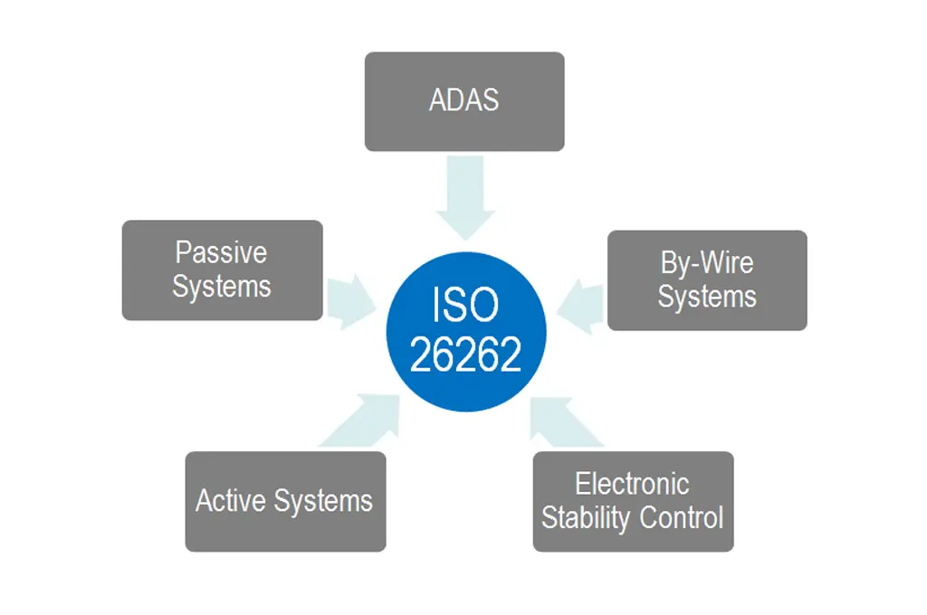
Functional safety is an immutable requirement for critical automotive systems. As such, in November 2011 the ISO 26262 standard was introduced defining the safety aspects for development of electric and electronic automotive systems. ISO 26262 describes all requirements to achieve functional safety. As an example: compliant systems must be able to identify their malfunctions and mitigate the effects such that passenger safety is preserved. Compliance with the standard is achieved between vehicle manufacturers, Tier 1 automotive suppliers, semiconductor suppliers and IP providers.

RelatedPosts

Researchers Enhanced 2D Ferromagnets Performance

Bourns Releases Two High Current Common Mode Choke Models

Electronics Weekly Announcing Finalists for Elektra Awards 2025

The standard describes four automotive safety integrity levels (ASILs) ranging from level A, for the lowest integrity requirements and steps up through levels B and C to D, for the highest integrity requirements – which in turn define the various processes that automotive development teams must use to meet the standard. An ISO 26262 development flow sits alongside the main design flow and ensures that the SoC or associated IP meets the required functional safety level. Design teams working to meet ISO 26262 standards must systematically analyze the status of any component or system throughout the supply chain.

ISO 26262 quickly became the guiding standard for functional safety for the automotive development process. But in the seven years since 26262 was published much has changed: intensified use of car sharing services, development of Advanced Driver Assistance Systems (ADAS) and the emergence of self-driving vehicles, to name just three key technology drivers.

With automotive progress has come greater need for absolute certainty that electronic systems are going to perform as intended without malfunctioning. Autonomous vehicles, for example, bring the challenge of not just functional safety but fail-operational functionality, sometimes also referred to as fault-tolerance, where a failure in one component does not stop the whole system from working correctly – the system is expected to reconfigure itself as necessary to ensure that it does so.

Rapid progress in the development of ADAS and autonomous driving technology is now challenging the semiconductor industry to bring the rigorous safety standards used in the automotive industry to its design process.

The problem is that while ISO 26262 included a section on hardware development, the standard previously had no specific guidelines for semiconductors themselves.

Until now. A new second edition will be released this year and perhaps not long after you read this. Designated ISO 26262:2018 it will add two additional parts to the original standard. Importantly, in Part 11 this second edition will lay out guidelines for the application of ISO 26262 requirements to semiconductor development. Part 11 also addresses intellectual property (IP), specifically for ISO 26262-related silicon IP suppliers. Part 11 has been written to ensure that the 20662 standard remains relevant when applied to systems commonly used in ADAS and fully autonomous driving architectures. In this way it could help to close any safety gaps now appearing during on autonomous driving tests.

Part 11 guideline provides detailed information to help semiconductor manufacturers develop ISO 26262 compliant parts. The section has tips, recommendations, and examples for creating ISO 26262 compliant ICs and IP, and includes information on failure rates and transient faults, as well as specifying diagnostic coverage.

The update has numerous other changes, including sections on improving cybersecurity functional safety. Part 12 of the second edition adds specific content for motorcycles, trucks, buses, trailers and semi-trailers.

This forthcoming release will bring significantly more information to support semiconductor suppliers In the areas of digital and analog components, programmable logic devices (PLDs), multi-core processors and sensors and as well as silicon IP.

Let’s look at these one at a time:

  • The sub-section on digital components provides detailed definitions and guidance on fault models of components such as memories, discusses failure modes of common digital blocks, and shows how to estimate diagnostic coverage. It describes digital blocks, helps to determine failure rates, explains qualitative and quantitative analysis techniques and talks about use of verification via fault injection simulation.
  • In Analog and Mixed Signal Part 11 covers how to divide up an analog device to aid safety analysis and discusses potential failure modes, discusses Analog Single Event Transients (ASET) and under and overvoltage diagnostics Guidance is provided on the level of safety analysis required and examples of failure modes for common analog blocks given.
  • Functional safety must be considered both while developing and using a configurable component. Part 11 offers information on types of PLDs, shows the hardware assumptions generated by the PLD manufacturer that must be validated by the PLD user and highlights key failure modes and associated safety mechanisms. It also discusses avoidance of systematic faults and verification techniques.
  • In the sub-section on multicore Part 11 provides an introduction to the topic of multi-core components. It goes over the safety requirements previously allocated to separate hardware components, now allocated to a single multi-core component. Particular attention is paid to freedom from interference in multi-core components.
  • Sensors and transducers, covered in detail in ISO 26262 for the first time, starts with a general overview of sensors, failure modes, and production processes. It addresses Micro Electro Mechanical System (MEMS) functional safety evaluation and strives to clarify sensor failure modes and transducer failure modes and gives examples of root causes.
  • Since ICs typically contain intellectual property (IP) from suppliers (flash memory, standard cells, microcontrollers) Part 11 addresses IP, in particular with regard to any ISO 26262-related IP with one or more allocated safety requirements. It describes know how to handle all variations of IP and issues guidance for integrating in-context IP and pre-existing Safety Element out of Context (SEooC) IP. The section describes safety analysis content for different IP types and speaks to how other sections of ISO 26262 have been adapted to support IP.

Of course any automotive application also must meet the automotive reliability requirements defined by the Automotive Electronics Council’s AEC-Q100 “Stress Test Qualification for Packaged Integrated Circuits,” AEC Q101 for discrete parts, AEC-Q102 for Discrete Optoelectronics, AEC-Q104 for Multichip Modules and AEC-Q200 for passive components.


Related

Recent Posts

Bourns Releases Two High Current Common Mode Choke Models

16.9.2025
5

SCHURTER Releases High Performance EV-Fuse

15.9.2025
5

TDK Releases 140C Compact Vibration Robust Automotive Aluminum Capacitors

5.9.2025
32

Samsung MLCCs Lineup for In-Vehicle Infotainment

4.9.2025
37

Littelfuse Adds 600W Automotive TVS Diodes for High-Energy Transient Protection

2.9.2025
14

Vishay Releases Harsh Environment Robust DC-Link Film Capacitor

2.9.2025
38

Bourns Releases Automotive High Creepage and Clearance Transformer

1.9.2025
33

Bourns Unveils Metal Powder Core High Current Low DCR Shielded Power Inductor

29.8.2025
38

Samsung Extends Capacitance of MLCC 0805 X7T 250V to 100nF

28.8.2025
34

Vishay Releases High Current 3.3 V to 36 V ESD Protection Diodes

25.8.2025
15

Upcoming Events

Sep 22
September 22 @ 13:00 - September 25 @ 15:15 EDT

Pre Cap Visual Inspection per Mil-Std-883 (TM 2017)

Sep 30
September 30 @ 12:00 - October 2 @ 14:00 EDT

MIL-Std-883 TM 2010

Oct 17
12:00 - 14:00 EDT

External Visual Inspection per MIL-STD-883 TM 2009

Oct 20
October 20 - October 23

Digital WE Days 2025 – Virtual Conference

Oct 21
October 21 @ 12:00 - October 23 @ 14:15 EDT

Space and Military Standards for Hybrids and RF Microwave Modules

View Calendar

Popular Posts

  • Buck Converter Design and Calculation

    0 shares
    Share 0 Tweet 0
  • Boost Converter Design and Calculation

    0 shares
    Share 0 Tweet 0
  • Flyback Converter Design and Calculation

    0 shares
    Share 0 Tweet 0
  • LLC Resonant Converter Design and Calculation

    0 shares
    Share 0 Tweet 0
  • Dual Active Bridge (DAB) Topology Explained

    0 shares
    Share 0 Tweet 0
  • Ripple Current and its Effects on the Performance of Capacitors

    3 shares
    Share 3 Tweet 0
  • What is a Dielectric Constant and DF of Plastic Materials?

    4 shares
    Share 4 Tweet 0
  • SEPIC Converter Design and Calculation

    0 shares
    Share 0 Tweet 0
  • How to Design an Inductor

    0 shares
    Share 0 Tweet 0
  • Core Materials, Permeability and Their Losses

    0 shares
    Share 0 Tweet 0

Newsletter Subscription


Passive Components Blog

© EPCI - Leading Passive Components Educational and Information Site

  • Home
  • Privacy Policy
  • EPCI Membership & Advertisement
  • About

No Result
View All Result
  • Home
  • Knowledge Blog
  • Premium Suppliers

© EPCI - Leading Passive Components Educational and Information Site

This website uses cookies. By continuing to use this website you are giving consent to cookies being used. Visit our Privacy and Cookie Policy.
Go to mobile version