Passive Components Blog
No Result
View All Result
  • Home
  • NewsFilter
    • All
    • Aerospace & Defence
    • Antenna
    • Applications
    • Automotive
    • Capacitors
    • Circuit Protection Devices
    • electro-mechanical news
    • Filters
    • Fuses
    • Inductors
    • Industrial
    • Integrated Passives
    • inter-connect news
    • Market & Supply Chain
    • Market Insights
    • Medical
    • Modelling and Simulation
    • New Materials & Supply
    • New Technologies
    • Non-linear Passives
    • Oscillators
    • Passive Sensors News
    • Resistors
    • RF & Microwave
    • Telecommunication
    • Weekly Digest

    Bourns Releases High Current Metal Alloy-based, Multilayer Power Chip Inductors

    Smiths Interconnect Extends Space-Qualified, High-Reliability Fixed Chip Attenuators 

    Samtec Expands Offering of Slim, High-Density HD Array Connectors

    Bourns Unveils High-Precision Wirewound Resistor with Long-Term Stability

    Common Mode Chokes Selection for RF Circuits in Next-Generation Communication Systems

    Capacitor Self-balancing in a Flying-Capacitor Buck Converter

    Littelfuse Acquires Basler Electric Enhancing High-Growth Industrial Market

    DigiKey Grows Inventory with Over 31K New Stocking Parts in Q3 2025

    Murata Expands Automotive Metal Frame Y2/X1 Safety MLCC Capacitors to 500V

    Trending Tags

    • Ripple Current
    • RF
    • Leakage Current
    • Tantalum vs Ceramic
    • Snubber
    • Low ESR
    • Feedthrough
    • Derating
    • Dielectric Constant
    • New Products
    • Market Reports
  • VideoFilter
    • All
    • Antenna videos
    • Capacitor videos
    • Circuit Protection Video
    • Filter videos
    • Fuse videos
    • Inductor videos
    • Inter-Connect Video
    • Non-linear passives videos
    • Oscillator videos
    • Passive sensors videos
    • Resistor videos

    Common Mode Chokes Selection for RF Circuits in Next-Generation Communication Systems

    Capacitor Self-balancing in a Flying-Capacitor Buck Converter

    How to Select Ferrite Bead for Filtering in Buck Boost Converter

    Power Inductors Future: Minimal Losses and Compact Designs

    Percolation Phenomenon: Degradation of Molded Power Inductors in DC/DC Converters

    Connector PCB Design Challenges

    Efficient Power Converters: Duty Cycle vs Conduction Losses

    Ripple Steering in Coupled Inductors: SEPIC Case

    SEPIC Converter with Coupled and Uncoupled Inductors

    Trending Tags

    • Capacitors explained
    • Inductors explained
    • Resistors explained
    • Filters explained
    • Application Video Guidelines
    • EMC
    • New Products
    • Ripple Current
    • Simulation
    • Tantalum vs Ceramic
  • Knowledge Blog
  • Suppliers
    • Who is Who
  • PCNS
    • PCNS 2025
    • PCNS 2023
    • PCNS 2021
    • PCNS 2019
    • PCNS 2017
  • Events
No Result
View All Result
Passive Components Blog
No Result
View All Result

Basic Filter Circuits Explained

4.1.2023
Reading Time: 8 mins read
A A

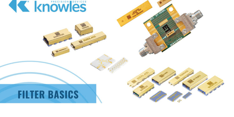
This article published by Knowles Precision Devices Blog explains some basic filter circuit background information on how filters do what they do.

Regardless of the technology behind the filter, there are several key concepts that all filters share that we will dive into throughout this series.

RelatedPosts

Knowles Releases High Q Non-Magnetic X7R MLCCs for Medical Imaging

Knowles Unveils High-Performance Safety-Certified MLCC Capacitors

Knowles Releases Inductors for Mission-Critical RF Applications

At the most basic level, filters are necessary in RF devices so that unwanted frequencies do not pass through the circuit and cause interference. While filtering can become quite complex as operating frequencies increase, it can be made much less daunting by having an understanding of how basic filters are built using standard electrical components such as resistors (Rs), capacitors (Cs), and inductors (Ls).

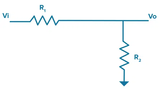
Before we jump into types of filters though, let’s start by looking at how a voltage divider functions. A voltage divider is a passive linear circuit that produces an output voltage (Vo) that is a fraction of the input voltage (Vi). As shown in Figure 1, the voltage divider changes the Vi down to the Vo based on the values of the resistors used, which are R1 and R2 below.

Figure 1. An illustration of the very familiar DC circuit, the voltage divider.

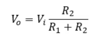
If we start with Ohms Law, which as a reminder, states that electric current is proportional to voltage and inversely proportional to resistance since resistance hinders the flow of current in the circuit, we can derive the following formula for how a voltage divider works:

voltage divider equation [1]

As you can see from the formula above, as R1 grows (or as R2 shrinks) the output voltage will drop.

Swapping Rs and Cs to Turn Our Voltage Divider into a Filter

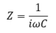
Now that we know how our simple voltage divider works, let’s look at what happens if we trade out some Rs for Cs. Impedance of a capacitor will change with frequency and that capacitance can be calculated as follows:

capacitance (capacitive impedance) equation [2]
  • Z = Impedance
  • Omega = Angular Frequency
  • i is the imaginary number since we are using complex numbers here
  • C = Capacitance

Thus, for a capacitor, impedance decreases with frequency. So, if we swap R2 for a C as shown in Figure 2, we will have a low-pass RC filter, which is a filter circuit that passes frequency signals below a certain cutoff frequency and blocks frequency signals higher than that point.

RC Low Pass Filter

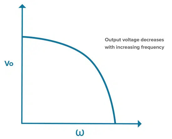
In the RC low-pass filter, the path to ground goes through a capacitor, which means impedance will decrease with increasing frequency. Therefore, in this circuit, the ratio of the Vi down to the Vo will depend on the values of R and C and the frequency of the signal. With high frequencies, impedance is low and energy is sent to ground as Vi is divided down. Low frequencies see a higher impedance and energy is sent to the output.

Figure 2. A diagram of an RC low-pass filter.
Figure 3. Output voltage decreases with increasing frequency in an RC low-pass filter.

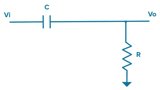
If we do this the other way around and replace R1 with a C, the path to output goes through the capacitor and we get the opposite effect.

RC High Pass Filter

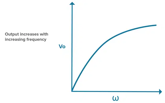
In this configuration, low frequencies see impedance that is higher than R, so the low-frequency signals go to ground while the high-frequency signals see an impedance lower than R, which means we get a high-frequency output.

Figure 4. A diagram of an RC high-pass filter.
Figure 5. Output voltage increases with increasing frequency when using a high-pass RC filter.

Swapping Cs and Ls to Create Your Desired Filter

Inductors have the opposite response to frequency than capacitors. This can be calculated as follows:

inductance (inductive impedance) equation [3]

L = Inductance

This means that impedance increases with frequency in an inductor. To create a low-pass filter using an R and L, we can start with an RC high-pass filter as shown in Figure 4 and swap the C for an L. We can also take the same type of approach to design a high-pass filter if we start with a RC low-pass filter as shown in Figure 2 and replace the C with an L. Both examples are illustrated in Figure 6.

Figure 6. In the top diagram, a low-pass filter is converted to a high-pass filter by swapping the C for an L in the path to ground. In the bottom diagram, the high-pass filter is converted to a low-pass filter by swapping the C for an L in the output line.

As it turns out, RC filters don’t provide the best performance in terms of roll off, which is the slope over frequency from passing a signal to blocking it. To improve this, RF designers can combine Cs and Ls, balancing their opposite responses to frequency to build different low-pass, high-pass, and band pass LC filter responses as shown in Figure 7.

Figure 7. Different types of LC filters and their frequency responses.

Manipulating Impedance to Achieve a Desired Frequency Response in Your Filter

Figure 8. In this example, L and C are replaced with impedances Z1 and Z2.

Given that Rs, Cs, and Ls offer different variations on impedance, we can think of designing a filter response as manipulating different impedances to achieve a desired frequency response. Thinking back to the DC voltage divider we started with at the beginning of this post, we can build on this to create a high pass circuit by adding networks of impedance (Zs) using various combinations of RCs and LCs as discussed throughout this post. Figure 8 below shows a high pass circuit where Z1 decreases with frequency and Z2 increases with frequency. In general, by replacing individual Rs, Cs, and Ls with sections of a circuit that have very specific impedance vs frequency behavior, we can create more complex high-performance filters.

By breaking down the different ways to use the frequency dependencies of Cs and Ls, you can see how it is possible to get a variety of different filter responses and form simple filters that can serve as the building blocks for more complex filtering needs.


Five key filter specifications to understand and check can be followed in related article here.

Related

Source: Knowles Precision Devices

Recent Posts

Common Mode Chokes Selection for RF Circuits in Next-Generation Communication Systems

30.10.2025
7

Capacitor Self-balancing in a Flying-Capacitor Buck Converter

30.10.2025
12

How to Select Ferrite Bead for Filtering in Buck Boost Converter

23.10.2025
42

Power Inductors Future: Minimal Losses and Compact Designs

30.10.2025
53

Percolation Phenomenon: Degradation of Molded Power Inductors in DC/DC Converters

30.10.2025
55

High Energy Density Polymer Film Capacitors via Molecular and Interfacial Design

15.10.2025
37

Over-Voltage Protection Clippers, Clampers, Snubbers, DC Restorers

13.10.2025
42

Silicon Capacitors Market: Shaping the Foundation for Next-Gen Miniaturization Electronics

10.10.2025
92

Enhancing Energy Density in Nanocomposite Dielectric Capacitors

9.10.2025
44

Advances in the Environmental Performance of Polymer Capacitors

8.10.2025
74

Upcoming Events

Nov 4
10:00 - 11:00 PST

Design and Stability Analysis of GaN Power Amplifiers using Advanced Simulation Tools

Nov 4
November 4 @ 12:00 - November 6 @ 14:15 EST

Wirebond Materials, Processes, Reliability and Testing

Nov 6
14:30 - 16:00 CET

Self-healing polymer materials for the next generation of high-temperature power capacitors

View Calendar

Popular Posts

  • Buck Converter Design and Calculation

    0 shares
    Share 0 Tweet 0
  • Boost Converter Design and Calculation

    0 shares
    Share 0 Tweet 0
  • LLC Resonant Converter Design and Calculation

    0 shares
    Share 0 Tweet 0
  • Flyback Converter Design and Calculation

    0 shares
    Share 0 Tweet 0
  • Ripple Current and its Effects on the Performance of Capacitors

    3 shares
    Share 3 Tweet 0
  • MLCC and Ceramic Capacitors

    0 shares
    Share 0 Tweet 0
  • Dual Active Bridge (DAB) Topology

    0 shares
    Share 0 Tweet 0
  • SEPIC Converter Design and Calculation

    0 shares
    Share 0 Tweet 0
  • What is a Dielectric Constant and DF of Plastic Materials?

    4 shares
    Share 4 Tweet 0
  • Flying Capacitors

    0 shares
    Share 0 Tweet 0

Newsletter Subscription


Passive Components Blog

© EPCI - Leading Passive Components Educational and Information Site

  • Home
  • Privacy Policy
  • EPCI Membership & Advertisement
  • About

No Result
View All Result
  • Home
  • Knowledge Blog
  • PCNS

© EPCI - Leading Passive Components Educational and Information Site

This website uses cookies. By continuing to use this website you are giving consent to cookies being used. Visit our Privacy and Cookie Policy.
Go to mobile version