


This post is based on TDK tech article that highlights benefits of MLCC ceramic capacitors over film capacitors in resonant circuits.
In resonant circuits used for wireless chargers and DC-DC converters, film capacitors have traditionally been used.
However, advancements in the capacity expansion and high voltage resistance of Multilayer Ceramic Capacitors (MLCCs) have made it possible to replace film capacitors with MLCCs in these applications.
Switching from film capacitors to MLCCs offers benefits such as miniaturization and reduced losses.
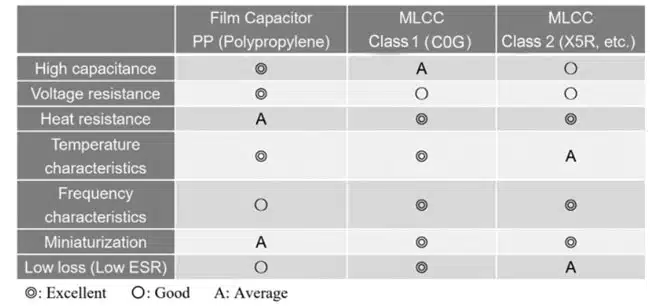
Capacitor Characteristics by Type
MLCCs are broadly classified into Class 1 (temperature compensating) and Class 2 (high dielectric constant) based on the ceramic dielectric material used as the dielectric.
Class 2 MLCCs are characterized by their large capacitance but have the disadvantage of a significant change rate in capacitance with temperature. On the other hand, Class 1 MLCCs (e.g. C0G), do not offer the high capacitance of high dielectric constant types but have a smaller rate of capacitance change with temperature and also exhibit superior frequency characteristics, making them suitable for use in circuits where high precision is required.
Class 1 MLCCs, represented by the C0G characteristic, traditionally overlapped only slightly with the area of film capacitors. However, recent advances in high voltage resistance and increased capacitance have rapidly expanded their overlapping area.
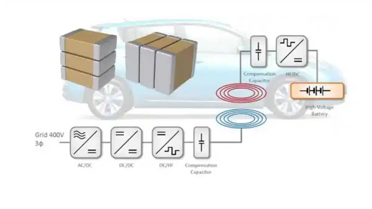
Key Characteristics Required for Capacitors in Resonant Circuits
In resonant circuits, capacitors are key components as they resonate with coils. The following characteristics are essential for capacitors used in resonance:
- Excellent Temperature Characteristics The resonant frequency is expressed by f=1/(2π√LC). Therefore, changes in capacitance due to temperature variations can lead to fluctuations in the resonant frequency, causing a reduction in power efficiency.Therefore, it is crucial to have minimal characteristic changes due to temperature variations.
- Superior Voltage Resistance Characteristics The capacitor and coil resonate, reducing the impedance of the resonant circuit and allowing a large current to flow, resulting in a large voltage being applied to the capacitor. Hence, capacitors must have sufficiently high voltage resistance (rated voltage) characteristics.
- Exceptional ESR Characteristics Since large currents flow through the capacitors, outstanding ESR (Equivalent Series Resistance) characteristics are necessary to minimize losses. The smaller the capacitor’s ESR or tanδ, the smaller the capacitor loss.
Polypropylene film capacitors and Class 1 MLCCs meet these conditions and have been used as capacitors for resonant circuits. Particularly, Class 1 MLCCs, with their small changes in capacitance due to temperature, low losses, compact size, and low profile, are increasingly being chosen to replace film capacitors.
Evaluation Example of Wireless Chargers
We introduce an evaluation example focused on resonant capacitors for wireless chargers intended for smartphones.
Evaluation Configuration
Qi-compatible wireless charger for smartphones
Input: 5V/2A
Output: 5W
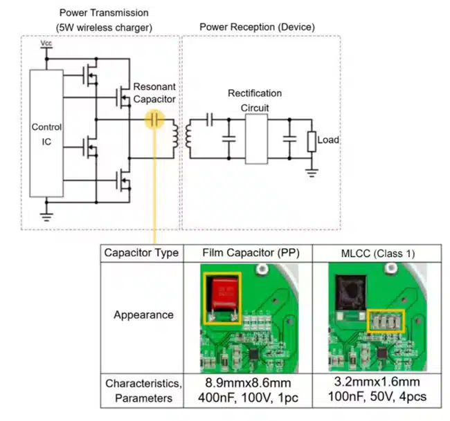
We compared the changes in efficiency and mounting area of the charger when switching the type of capacitor used. Figure 1. shows a schematic diagram of the wireless charger’s resonant circuit and the capacitors used for evaluation.
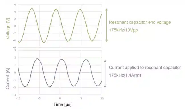
Voltage & Current Waveforms Applied to the Resonant Capacitor
Figure 2. shows the voltage and current applied to the resonant capacitor. It can be observed that the voltage and current waveforms applied to the resonant capacitor closely approximate a sine wave. Losses occur in resonant capacitors conducting alternating ripple current. To suppress these losses, the capacitor’s ESR must be low.
Comparison of capacitor loss and power efficiency in actual equipment
Figure 3. compares the ESR of film capacitors (PP) and A comparison of the ESR of the MLCC (Class 1), the ESR of the resonant capacitor, and the calculated loss in the entire resonant capacitor is shown. The ESR of Class 1 MLCCs is approximately an order of magnitude lower than that of film capacitors. Since capacitor loss is expressed as ESR x I2, it is considered that a lower ESR in capacitors can reduce losses in the resonant circuit.
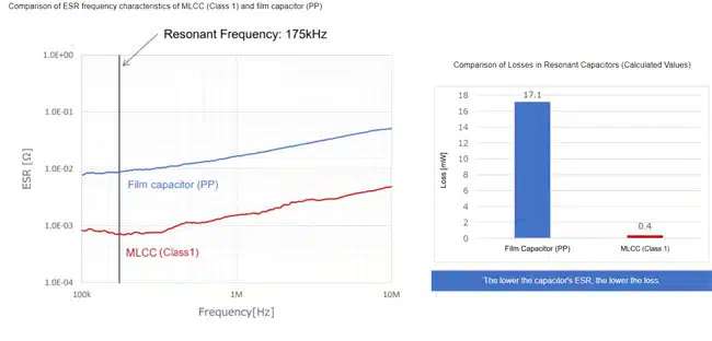
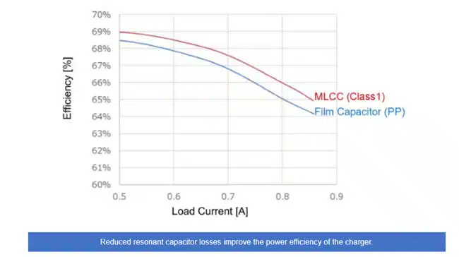
Figure 4. below shows the results of measuring the power efficiency of the wireless charger. When we measured the power efficiency while changing the load current of the wireless charger, we confirmed that Class 1 MLCC has an efficiency improvement of approximately 1% compared to a film capacitor.
Comparison of Mounting Area
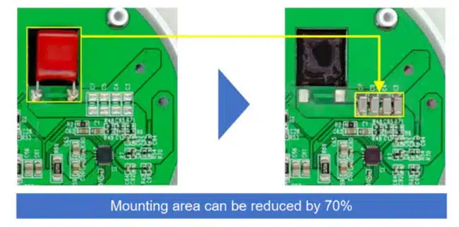
As shown in Figure 5. since MLCCs are smaller than film capacitors, the mounting area can be reduced.
Summary
Using resonant capacitors for wireless chargers as an example, we compared losses and mounting areas for each type of capacitor.
– Due to their low ESR, Class 1 MLCCs can reduce the electrical performance and mounting area in resonant capacitors, contributing to improved power efficiency.
– Class 1 MLCCs are more compact and have a lower profile compared to film capacitors, making it possible to further reduce the size of the assembly.
Accordingly, Class 1 MLCCs, represented by C0G, are suitable for use as resonant capacitors, enabling improvements in power efficiency and miniaturization.
Further read: MLCCs in Wireless Power Transfer Resonant Circuits


