


This article explains some basic capacitor selection guide for coupling and decoupling applications.
Key Takeaways
- Capacitors are essential in electronic circuits, influencing performance for coupling and decoupling applications.
- Coupling capacitors allow AC signals to pass while blocking DC components, enhancing audio and radio frequency quality.
- When selecting a coupling capacitor, consider capacitance value, voltage rating, and equivalent series resistance (ESR).
- Tantalum and aluminium electrolytic capacitors are popular for coupling applications due to their stability and cost-effectiveness.
- Decoupling capacitors stabilize voltage and clean DC signals by absorbing excess energy or shunting unwanted AC components.
Capacitors are fundamental components in both analog and digital electronic circuits. These passive components play an important role in influencing the operational behavior of circuits. The characteristics of a capacitor vary mainly depending on the dielectric material used. The dielectric material determines the capacitance value, energy efficiency, and size of a capacitor. Fixed value capacitors can be broadly categorized into two: polar (electrolytic) and non-polar (electrostatic) capacitors. Non-polar capacitors include ceramic, film, and paper capacitors. Aluminium electrolytic capacitors and tantalum capacitors are polar components.
In circuits, capacitors are used for a wide range of applications including storing electrical charges, blocking DC components, bypassing AC components, filtering unwanted signals, and so on. The applications of a capacitor primarily depend on its characteristics. Key properties to consider when selecting a capacitor for a given application include capacitance value, voltage rating, frequency response characteristics, cost, and physical size. Other properties of a capacitor that can influence the performance of an electronic circuit include temperature characteristics, self-healing properties, aging, and flammability.
Filtering Principles
Filtering capacitors, often combined with inductors, attenuate high-frequency noise and switching ripple. In DC-DC converters, input capacitors reduce ripple from the supply, while output capacitors smooth the regulated voltage. Capacitor technology selection (ceramic, tantalum, polymer, electrolytic) depends on frequency response, ESR, and cost considerations.
Impedance and Frequency Response
The impedance of a capacitor is frequency-dependent. At low frequencies, capacitance dominates; at resonance, impedance is minimized; at high frequencies, parasitic inductance dominates. Designers must combine capacitors of different values to cover a wide frequency spectrum.
| Capacitor Type | Strengths | Limitations | Typical Use |
|---|---|---|---|
| Ceramic (MLCC) | Low ESR/ESL, excellent HF response | Capacitance derating with bias | High-frequency decoupling |
| Tantalum Polymer | Stable capacitance, low ESR | Voltage derating required | Mid-frequency decoupling |
| Aluminum Electrolytic | High capacitance, low cost | High ESR, poor HF response | Bulk energy storage |
| Film | Stable, low loss | Bulky, limited low-voltage use | Specialized filtering |
Cascading and Anti-Resonance
Using multiple capacitors in parallel reduces impedance across a broad frequency range. However, mixing values introduces anti-resonance peaks, where impedance spikes due to interaction between capacitors. Designers mitigate this by carefully selecting capacitance ratios and using multiple intermediate values.
Coupling Capacitors
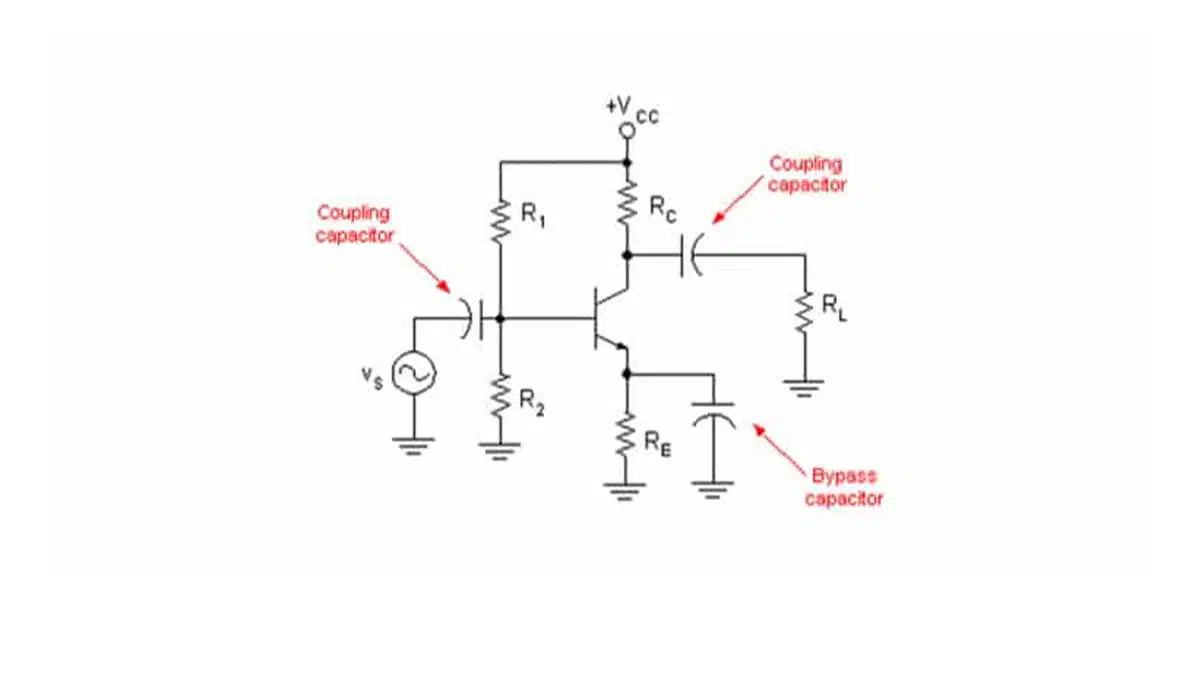
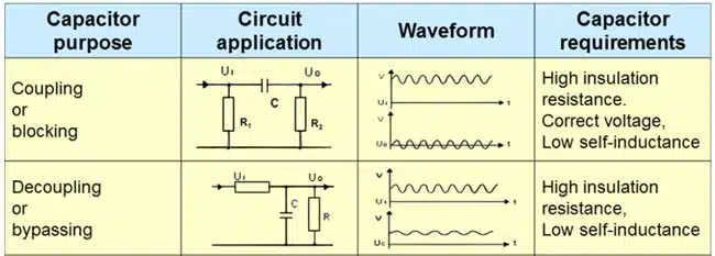
Coupling capacitors are used in electronic circuits to pass the desired AC signal and block unwanted DC components. These unwanted DC signals come from electronic devices or preceding stages of an electronic circuit. In audio systems, DC components affect the quality of the desired signal by introducing noise. Furthermore, DC signals affect the performance of power amplifiers and increase distortion. In circuits, a coupling capacitor is connected in series with the signal path. Coupling capacitors are used in analog as well as digital electronic circuits. They find many applications in audio and radio frequency systems.
The reactive nature of a capacitor allows it to respond to different frequencies differently. In coupling applications, a capacitor blocks low frequency DC signals and allows high frequency AC signals to pass. To low frequency components, such as the DC signals, a capacitor exhibits high impedance, thereby blocking them. On the other hand, a capacitor exhibits low impedance to high frequency components. This allows high frequency signals such as AC components to pass.
In audio systems, DC sources are used to power audio circuits. However, since the audio signal is usually an AC signal, the DC component is unwanted on the output. To prevent the DC signal from appearing on the output device, a coupling capacitor is added in series with the load.
Coupling capacitors are essential components in amplifier circuits. They are used to prevent interference of a transistor’s bias voltage by AC signals. In most amplifier circuits, this is achieved by driving the signal to the base terminal of a transistor through a coupling capacitor. When a capacitor with the correct capacitance value is serially connected, the useful signal is allowed to pass while the DC component is blocked.
Presence of DC components on a transmission line can significantly affect the performance of a digital circuit. In communication systems, coupling capacitors are used to block unwanted DC components. Blocking the DC component helps to minimize energy loss and prevent accumulation of charge in digital circuits.
Types of capacitors for coupling applications
When selecting a capacitor for coupling/DC blocking applications, the key parameters to consider include impedance, equivalent series resistance, and series resonant frequency. The capacitance value primarily depends on the frequency range of the application and the load/source impedance. The types of capacitors that are commonly used for coupling applications include film, ceramic, tantalum, aluminium electrolytic, and aluminium organic/polymer electrolytic capacitors.
Tantalum capacitors offer high stability at high capacitance values, and they are available in different variants. As compared to ceramics, these capacitors have higher ESR and are more expensive. For coupling applications, tantalum capacitors are more popular than ceramic capacitors.
Aluminium electrolytic capacitors are cheaper than tantalum capacitors. They offer stable capacitance and have ESR characteristics similar to tantalum capacitors. However, these capacitors are relatively large in size and not recommended for circuits with limited circuit board space. Aluminium electrolytic capacitors are widely used for coupling applications in power amplifiers.
Ceramic capacitors are inexpensive and available in small SMT packages. These capacitors are cheaper compared to tantalum capacitors. Although ceramic capacitors are commonly used in audio and RF applications, they are generally unsuitable for applications that demand superior performance.
The large physical sizes of film capacitors limit their applications in AC coupling. If space is not an issue, polypropylene and polyester capacitors have characteristics that make them a good choices for coupling applications in pre-amp circuits.
Decoupling Capacitors
Decoupling capacitors provide a low-impedance path for transient currents, stabilizing supply voltage at the IC pins. Their placement close to the load minimizes parasitic inductance. The effectiveness of decoupling is quantified by the target impedance, which ensures voltage ripple remains within acceptable limits during load transients.
Some electronic circuits are highly sensitive to voltage spikes, and rapid voltage changes can greatly affect their performance. Decoupling capacitors are used in electronic circuits to prevent quick voltage changes by acting as electrical energy reservoirs. In case of a sudden voltage drop, a decoupling capacitor provides the electrical energy required to maintain a stable voltage supply. On the other hand, if there is a sudden voltage spike, the capacitor stabilizes voltage by absorbing the excess energy.
Apart from stabilizing voltage in electronic circuits, decoupling capacitors are also used to allow DC components to pass while shorting AC components to ground. Capacitors that are used for bypassing AC noise in electronic circuits are also commonly known as bypass capacitors. Bypass capacitors absorb AC noise to produce a cleaner DC signal.
To remove AC noise, a bypass capacitor is placed in parallel with a resistor. A capacitor offers high resistance to low frequency signals and less resistance to high frequency signals. As such, low frequency DC components use the resistor path while high frequency AC components are shunted to ground through the bypass capacitor. This yields a clean DC signal that is free from AC components.
Power Integrity
Power integrity refers to the ability of the PDN to deliver clean, stable power to ICs under dynamic load conditions. The PDN consists of the voltage regulator module (VRM), PCB planes, vias, and decoupling capacitors. The goal is to maintain the supply voltage within tolerance limits during transient load events.
| PDN Element | Role | Impact on PI |
|---|---|---|
| VRM | Primary power source | Sets baseline impedance and stability |
| PCB Planes | Distribute current | Introduce parasitic inductance and resistance |
| Decoupling Capacitors | Provide local charge storage | Suppress noise, reduce ripple |
Target Impedance Concept
The target impedance defines the maximum allowable PDN impedance to keep voltage ripple within limits. It is derived from the maximum transient current and the allowable voltage deviation. Maintaining flat impedance across frequency ensures minimal resonance and stable operation.
PCB Parasitics and Optimization
PCB layout strongly influences capacitor effectiveness. Via inductance, plane spacing, and capacitor mounting geometry can degrade decoupling performance. Optimization strategies include:
- Using multiple vias to reduce inductance.
- Placing capacitors close to IC power pins.
- Employing thin dielectric layers to minimize loop inductance.
- Using EM simulation to capture real-world parasitics.
Flat Impedance Design
Flat impedance design minimizes resonance peaks by carefully selecting and distributing capacitors. Instead of relying on arbitrary capacitor values, designers calculate the required capacitance to cancel VRM and PCB inductance. This approach reduces the number of capacitors while improving PI robustness.
Types of capacitors for decoupling applications
When selecting a capacitor for decoupling applications, it is critical to consider the electrical requirements of the design. The key parameters to consider when selecting a bypass capacitor include the lowest frequency of the AC signal and resistance value of the resistor. In most cases, the lowest frequency is 50 Hz.
Although different types of capacitors are available for decoupling/bypassing applications, their characteristics vary markedly depending on the dielectric material used and structure. The two determine temperature stability, linearity, voltage rating, physical size and cost. The types of capacitors that are commonly used for decoupling applications include ceramic, tantalum, and aluminium electrolytic capacitors.
Capacitor selection involves balancing capacitance, equivalent series resistance (ESR), and equivalent series inductance (ESL). A mix of bulk capacitors (low-frequency stability) and ceramic capacitors (high-frequency decoupling) is typically required. Placement and via connection strategies significantly affect performance.
| Capacitor Type | Frequency Range | Typical Value | Role |
|---|---|---|---|
| Electrolytic / Polymer | kHz – low MHz | 10 µF – 1000 µF | Bulk energy storage |
| MLCC (Ceramic) | MHz – GHz | 0.01 µF – 10 µF | High-frequency decoupling |
Decoupling capacitors act as local energy reservoirs, supplying instantaneous current to ICs during transient events. Their effectiveness depends on minimizing impedance across the target frequency range. A common design goal is to keep the Power Distribution Network (PDN) impedance below a calculated target impedance.
| Capacitor Type | Frequency Range | Advantages | Limitations |
|---|---|---|---|
| Ceramic (Class I) | High frequency | Stable, low ESR/ESL | Low capacitance values |
| Ceramic (Class II/III) | Mid to high | High capacitance density | DC bias reduces effective C |
| Tantalum Polymer | Low to mid | Stable ESR, compact | Voltage derating required |
| Aluminum Polymer | Low to mid | Good ripple handling | Limited high-frequency response |
The performance and cost of ceramic capacitors make them a popular option for decoupling applications. These capacitors have low equivalent series resistance (ESR) and equivalent series inductance (ESL). In addition, multi-layer ceramic capacitors (MLCCs) are available in a wide range of packages and capacitance values. Ceramic capacitors are an excellent option for decoupling applications in HF circuits.
Switching type aluminium electrolytic capacitors are commonly used for decoupling applications in low frequency and medium frequency electronic circuits. These capacitors are inexpensive,available in a wide range of capacitance values, and have high capacitance-to-volume ratio. However, aluminium electrolytic capacitors exhibit temperature related wear out and have high ESR at low temperatures. These capacitors are widely used for decoupling applications in consumer products.
Solid tantalum capacitors have high CV, and they are less susceptible to wear out. Furthermore, they exhibit impressive stability at low temperatures. As compared to aluminium electrolytic capacitors, tantalum capacitors have higher capacitance-to-volume ratios and lower ESR. On the flip side, tantalum capacitors are expensive and limited to low voltage applications, usually up to 50 V. These capacitors are commonly used in higher reliability applications.
Film capacitors such as polyester, polypropylene, Teflon, and polystyrene capacitors have limited decoupling applications. Although these capacitors are suitable for high voltage applications and are less susceptible to wear out, the cost of producing them is relatively high. Nevertheless, the characteristics of these capacitors make them suitable options for high voltage, high current, and audio decoupling applications.
Practical Design Guidelines
- Use large-value capacitors (e.g., polymer) for low-frequency stability.
- Add mid-value ceramics (1 µF – 10 µF) to cover mid-frequency ranges.
- Include small-value ceramics (10 nF – 100 nF) for high-frequency decoupling.
- Place capacitors as close as possible to IC power pins.
- Account for DC bias derating in Class II/III ceramics.
Conclusion
Capacitors are fundamental components in both analog and digital electronic circuits. They are used for a wide range of applications including coupling, decoupling, filtering, and timing applications.
Decoupling and filtering are not interchangeable but complementary strategies in power delivery design. By combining capacitor technologies, managing parasitics, and targeting impedance across frequency bands, engineers can ensure stable, efficient, and noise-free operation of modern electronic systems. The balance between theory, simulation, and empirical validation remains the cornerstone of successful PDN design.
Decoupling capacitor optimization is essential for achieving robust power integrity in modern electronic systems. By applying the target impedance method, accounting for PCB parasitics, and leveraging flat impedance design, engineers can minimize noise, reduce EMI, and improve system reliability. The result is a cost-effective, high-performance PDN that meets the stringent demands of today’s high-speed digital designs.
Coupling capacitors allow AC components to pass while blocking DC components. Decoupling capacitors are used in electronic circuits as energy reservoirs to prevent quick voltage changes. Bypassing capacitors clean DC signals by shunting unwanted AC components to ground. A capacitor significantly determines the performance, lifetime, and reliability of an electronic circuit. As such, it is advisable to use high quality components, preferably from franchised distributors or direct from the manufacturer.
Related video:
FAQ: Coupling and Decoupling Capacitors
Coupling capacitors pass AC signals while blocking DC components, ensuring clean transmission in audio and RF circuits. Decoupling capacitors stabilize voltage by absorbing spikes and supplying energy during transients, improving power integrity in digital and analog systems.
Common choices include tantalum and aluminium electrolytic capacitors for stability and cost-effectiveness, ceramic capacitors for compact RF/audio use, and film capacitors for high-quality pre-amp circuits when space allows.
Designers typically combine bulk electrolytic or polymer capacitors for low-frequency stability with ceramic MLCCs for high-frequency noise suppression. Tantalum capacitors are used in high-reliability, low-voltage designs.
Placing capacitors close to IC power pins minimizes parasitic inductance, ensuring effective suppression of voltage ripple and maintaining stable power delivery.
How-to: Select Capacitors for Coupling and Decoupling
- Define the Application
Identify whether the capacitor is needed for coupling (signal transfer) or decoupling (power stabilization).
- Choose the Capacitor Type
For coupling: consider tantalum, aluminium electrolytic, or ceramic capacitors. For decoupling: use a mix of bulk electrolytic/polymer and ceramic MLCCs.
- Match Electrical Parameters
Check capacitance value, voltage rating, ESR, and frequency response to match the circuit’s requirements.
- Optimize Placement
Place decoupling capacitors as close as possible to IC power pins, and use multiple values in parallel to cover a wide frequency spectrum.
- Validate Performance
Simulate or measure impedance across frequency bands to ensure stable operation and compliance with target impedance design.


