Passive Components Blog
No Result
View All Result
  • Home
  • NewsFilter
    • All
    • Aerospace & Defence
    • Antenna
    • Applications
    • Automotive
    • Capacitors
    • Circuit Protection Devices
    • electro-mechanical news
    • Filters
    • Fuses
    • Inductors
    • Industrial
    • Integrated Passives
    • inter-connect news
    • Market & Supply Chain
    • Market Insights
    • Medical
    • Modelling and Simulation
    • New Materials & Supply
    • New Technologies
    • Non-linear Passives
    • Oscillators
    • Passive Sensors News
    • Resistors
    • RF & Microwave
    • Telecommunication
    • Weekly Digest

    High-Q RF & Microwave MLCCs: A Cross-Vendor Benchmark

    Molex Unveils Automotive Ethernet Connectors for Next‑Gen SDV Architectures

    TAIYO YUDEN Introduced Hybrid Aluminum Capacitors for 48V Automotive Power Supplies

    ECIA Industry Pulse June 2026 Reaches Five‑Year High

    YAGEO Announces July 2026 Capacitor Price Increase

    YAGEO Presents Single-Phase Common Mode Chokes for Industrial EMI Suppression

    Enabling the 800 V AI Server Era: How C0G High-Voltage MLCC Supports Next-Generation Power Architectures

    binder Prints Electronics on 3D Components Connector Surface

    Vishay Introduces SMD Polymer PTC Thermistors for Fast Resettable Overcurrent Protection

    Trending Tags

    • Ripple Current
    • RF
    • Leakage Current
    • Tantalum vs Ceramic
    • Snubber
    • Low ESR
    • Feedthrough
    • Derating
    • Dielectric Constant
    • New Products
    • Market Reports
  • VideoFilter
    • All
    • Antenna videos
    • Capacitor videos
    • Circuit Protection Video
    • Filter videos
    • Fuse videos
    • Inductor videos
    • Inter-Connect Video
    • Non-linear passives videos
    • Oscillator videos
    • Passive sensors videos
    • Resistor videos

    KYOCERA AVX Presents Antenna Integrator Studio Tutorial for Antenna Placement and RF Design

    Power Design Simulation Tools for Faster Inductor Selection and Loss Optimization

    EMC‑Compliant PCB and Connector Design Guidelines

    Why Isolated DC/DC Power Supplies Fail Late, Würth Elektronik Podcast

    Designing 800 V DC EMC Filters: Calculation, Simulation and Measurement

    Current Sense Transformer Datasheet and Design‑in Guide

    Designing a USB Type‑C Flyback Planar Transformer with Frenetic’s Planar Tool

    Magnetics Design in High‑Frequency GaN Converters

    Qi2 Wireless Charging: Inductors, Capacitors and EMC Filters

    Trending Tags

    • Capacitors explained
    • Inductors explained
    • Resistors explained
    • Filters explained
    • Application Video Guidelines
    • EMC
    • New Products
    • Ripple Current
    • Simulation
    • Tantalum vs Ceramic
  • Knowledge Blog
  • DossiersNew
  • Suppliers
    • Who is Who
  • PCNS
    • PCNS 2025
    • PCNS 2023
    • PCNS 2021
    • PCNS 2019
    • PCNS 2017
  • Events
No Result
View All Result
Passive Components Blog
No Result
View All Result

Capacitors Pre-charging in Drive Circuits Using Pulse-Withstanding Resistors

9.2.2023
Reading Time: 5 mins read
A A

This article published by Rutronik discusses pre-charging of capacitors using pulse-withstanding resistors in drive circuits.

Electric motors are usually controlled using converters. Electrolytic capacitors are frequently used to stabilize and buffer the DC voltage in the DC link.

RelatedPosts

Tantalum Polymer Capacitors Benefits in Decoupling Applications

Over-Voltage and Over-Current Protection Explained

Rutronik and Yageo Secure Long-Term Supply of MLCCs

There are a number of issues to consider with switching these capacitors in and out of the circuit.

When a capacitor is charged through a resistor, the increase in voltage follows a curve in the form of a natural exponential function (Figure 1, blue line). The relevant charging current of the capacitor (green) on the other hand takes the form of a decaying natural exponential function.

Figure 1. The voltage and charging current of a capacitor follow opposing natural exponential functions.

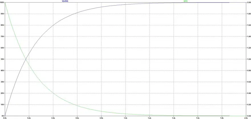
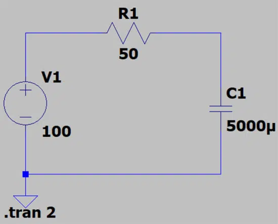
In an example of charging of 5000uF 100V capacitor through 50Ohm resistor (see Fig.2.) the maximum current flows right at the start of the charging process, at which point it is 100 V/50 Ω = 2 A. After around 1.5 seconds the capacitor reaches a voltage of close to 100 V, while the current is close to 0 A.

Figure 2. Charging a capacitor at 5,000 µF to a voltage of 100 V through a resistor of 50 Ω.

Let’s say this capacitor is charged without using a resistor, so that when the voltage is “hard switched,” there is only a very low specific resistance in the supply line—estimated to be 10 mΩ—in which case there is theoretically a current of up to 10,000 A at the first moment of charging!

However, in reality, in addition to the ohmic resistance of the connecting wire, there are other elements providing resistance:

  • the ohmic resistance of the capacitor estimated at around 25 mΩ
  • the internal resistance of the voltage source estimated at around 20 mΩ
  • the transfer resistance of the connecting terminals, switching contacts, etc. of max. 5  mΩ

This means that a realistic total resistance would be around 50 mΩ. With this, there is a still a peak current of over 2,000 A (100 V/0.05 Ω = 2,000 A).

While this very high current would only be flowing for a very brief moment, you can still imagine what impact these current surges can have on other components — certainly so, when you remember that DC voltages of 800 V are commonplace in DC link solutions for converters nowadays.

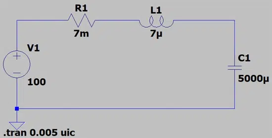
Switch-On Processes in Consideration of Wire Inductance

If we consider not only the capacitance but also any wire inductance as shown in Figure 3, we observe behavior such as that seen in Figure 4.

Figure 3. Charging a capacitor at 5,000 µF to a voltage of 100 V with a resistance of 7 mΩ and a wire inductance of 7 µH.
Figure 3. Behavior of a capacitor during charging, taking wire inductance into account.

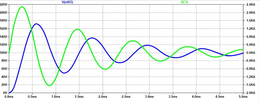
Without going into detail, the graph shows clearly that the voltage (blue curve) is no longer a natural exponential function, instead oscillating towards a value of around 100 V. Briefly, it will reach a value of up to 170 V, around 70% higher than the externally applied output voltage!

The current (green curve) also peaks at around 2,100 A just after switch-on due to the additional inductance.

In other words, the current reaches very high values and overvoltages with voltage surges of up to double the externally applied voltage possibly occurring even if all ohmic resistors, inductors, and capacitors to be charged in the charging circuit are accounted for.

This is why hard-switching a capacitor should always be avoided. Pre-charging a capacitor allows the aforementioned behavior to be almost entirely prevented.

Similar behavior occurs when discharging a capacitor, which is why it is also recommended to provide a resistor for the discharging process.

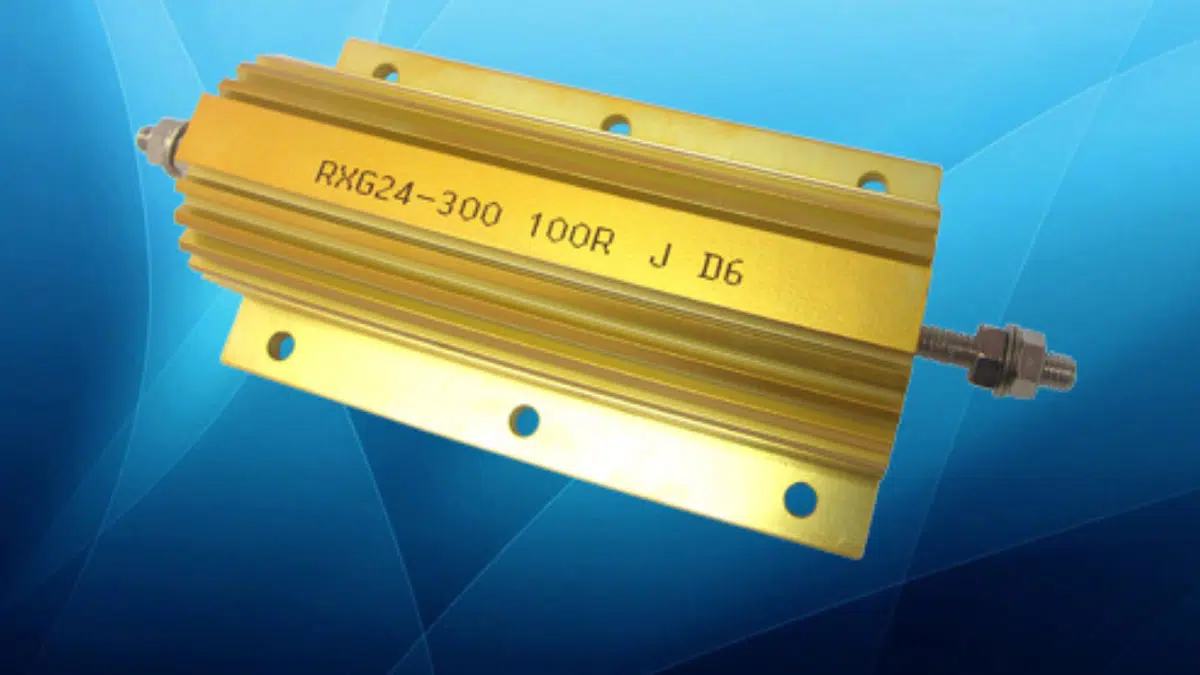
Pulse-Withstanding Pre-Charge Resistors

A very simple and cost-effective approach is provided here by pulse-withstanding charge resistors, which can be connected in series with the capacitor for a certain time. All that is needed here is a pre-charge branch connected in parallel to the main switch. This branch needs to fulfill the following requirements:

Use of the current-limiting effect of the resistor

Two-step switch-on process:            

  1. The pulse-withstanding resistor is used to pre-charge the capacitor until it has almost entirely reached the externally applied voltage level
  2. The capacitor is directly connected by bridging the pre-charge branch connected in parallel with the main switch

A mechanical or electrical lock-out mechanism that prevents switch-on without a pre-charge.

A wide range of pre-charge resistors is offered by leading power resistor manufacturers. These include cement-coated wire resistors from 3 to 18 W and high-load resistors with aluminum housing from tenths to hundreds W. Customized solutions can be often ordered as well for special requirements. For example, increased voltage requirements, special geometric forms, and also enhanced cooling solutions can be implemented.

Related

Source: Rutronik

Recent Posts

High-Q RF & Microwave MLCCs: A Cross-Vendor Benchmark

2.7.2026
12

TAIYO YUDEN Introduced Hybrid Aluminum Capacitors for 48V Automotive Power Supplies

2.7.2026
8

YAGEO Announces July 2026 Capacitor Price Increase

1.7.2026
89

Enabling the 800 V AI Server Era: How C0G High-Voltage MLCC Supports Next-Generation Power Architectures

1.7.2026
44

MLCCs in the Age of AI: Q2 2026 Market Tightness

30.6.2026
179

AI Hardware Demand for Passive Components Dossier

30.6.2026
68

Skeleton Supercapacitor Achieves UL‑certified 3,500 A Peak Current for AI Data Centers

26.6.2026
60

100 V Hybrid Polymer Capacitor from VINA Enesol Targets 48–72 V Power Platforms

26.6.2026
123

Using a Virtual Anode Thermal Model to Evaluate Miniaturization Risk in Tantalum Capacitors

24.6.2026
44

Upcoming Events

Jul 2
17:30 - 18:30 CEST

Can Claude design a production-ready Custom Magnetic Component?

Jul 14
16:00 - 17:00 CEST

EMC Design Essentials: Mastering Varistors and Common Mode Chokes

Jul 21
16:00 - 17:00 CEST

Safety by design: X and Y Interference suppression capacitors for power line filters

View Calendar

Popular Posts

  • Boost Converter Design and Calculation

    0 shares
    Share 0 Tweet 0
  • Buck Converter Design and Calculation

    0 shares
    Share 0 Tweet 0
  • LLC Resonant Converter Design and Calculation

    0 shares
    Share 0 Tweet 0
  • Flyback Converter Design and Calculation

    0 shares
    Share 0 Tweet 0
  • MLCC and Ceramic Capacitors

    0 shares
    Share 0 Tweet 0
  • Nvidia Vera Rubin: Why One AI Rack Needs So Many More MLCC Capacitors

    0 shares
    Share 0 Tweet 0
  • Earthing Systems and IEC Classification Explained

    0 shares
    Share 0 Tweet 0
  • Dual Active Bridge (DAB) Topology

    0 shares
    Share 0 Tweet 0
  • MLCC Case Sizes Standards Explained

    0 shares
    Share 0 Tweet 0
  • SEPIC Converter Design and Calculation

    0 shares
    Share 0 Tweet 0

Newsletter Subscription


Passive Components Blog

© EPCI - Leading Passive Components Educational and Information Site

  • Home
  • Privacy Policy
  • EPCI Membership & Advertisement
  • About

No Result
View All Result
  • Home
  • Knowledge Blog
  • Dossiers
  • PCNS

© EPCI - Leading Passive Components Educational and Information Site

This website uses cookies. By continuing to use this website you are giving consent to cookies being used. Visit our Privacy and Cookie Policy.
Go to mobile version