Passive Components Blog
No Result
View All Result
  • Home
  • NewsFilter
    • All
    • Aerospace & Defence
    • Antenna
    • Applications
    • Automotive
    • Capacitors
    • Circuit Protection Devices
    • electro-mechanical news
    • Filters
    • Fuses
    • Inductors
    • Industrial
    • Integrated Passives
    • inter-connect news
    • Market & Supply Chain
    • Market Insights
    • Medical
    • Modelling and Simulation
    • New Materials & Supply
    • New Technologies
    • Non-linear Passives
    • Oscillators
    • Passive Sensors News
    • Resistors
    • RF & Microwave
    • Telecommunication
    • Weekly Digest

    RF Inductors: Selection and Design Challenges for High-Frequency Circuits

    Wk 45 Electronics Supply Chain Digest

    Transformer Safety IEC 61558 Standard

    ESR of Capacitors, Measurements and Applications

    Murata Christophe Pottier Appointed President of EPCIA

    3-Phase EMI Filter Design, Simulation, Calculation and Test

    YAGEO Unveils Compact 2.4 GHz SMD Antenna

    KYOCERA AVX Releases Antenna for Iridium Satellite IoT Applications

    Molex Releases Industry-First Quad-Row Board-to-Board Connectors with EMI Shields

    Trending Tags

    • Ripple Current
    • RF
    • Leakage Current
    • Tantalum vs Ceramic
    • Snubber
    • Low ESR
    • Feedthrough
    • Derating
    • Dielectric Constant
    • New Products
    • Market Reports
  • VideoFilter
    • All
    • Antenna videos
    • Capacitor videos
    • Circuit Protection Video
    • Filter videos
    • Fuse videos
    • Inductor videos
    • Inter-Connect Video
    • Non-linear passives videos
    • Oscillator videos
    • Passive sensors videos
    • Resistor videos

    RF Inductors: Selection and Design Challenges for High-Frequency Circuits

    Transformer Safety IEC 61558 Standard

    3-Phase EMI Filter Design, Simulation, Calculation and Test

    Transformer Design Optimization for Power Electronics Applications

    Common Mode Chokes Selection for RF Circuits in Next-Generation Communication Systems

    Capacitor Self-balancing in a Flying-Capacitor Buck Converter

    How to Select Ferrite Bead for Filtering in Buck Boost Converter

    Power Inductors Future: Minimal Losses and Compact Designs

    Percolation Phenomenon: Degradation of Molded Power Inductors in DC/DC Converters

    Trending Tags

    • Capacitors explained
    • Inductors explained
    • Resistors explained
    • Filters explained
    • Application Video Guidelines
    • EMC
    • New Products
    • Ripple Current
    • Simulation
    • Tantalum vs Ceramic
  • Knowledge Blog
  • Suppliers
    • Who is Who
  • PCNS
    • PCNS 2025
    • PCNS 2023
    • PCNS 2021
    • PCNS 2019
    • PCNS 2017
  • Events
No Result
View All Result
Passive Components Blog
No Result
View All Result

Ceramic Capacitors in SMPS Circuits

1.11.2022
Reading Time: 11 mins read
A A

This technical blog article written by Kevin Cho, KYOCERA-AVX Components Corporation, explains the key parameters for designing ceramic capacitors in SMPS Circuits.

Capacitors are ubiquitous and indispensable components of electronic circuits used for a plethora of uses. For engineers looking to design multilayer ceramic capacitors (MLCCs) in switch-mode power supplies (SMPS) such as Buck and Boost converters, some essential parameters to be considered include the ripple current capability, ripple voltage, and power dissipation.

RelatedPosts

KYOCERA AVX Releases Antenna for Iridium Satellite IoT Applications

KYOCERA AVX Expands Stacked MLCC Capacitors Offering

KYOCERA Releases Shielded Board-to-Board Connectors for Reliable EMI Protection

Using the KYOCERA AVX SpiCalci10 model simulation tool for SMPS capacitors, this whitepaper will outline various MLCC characteristics, AC current capability, and other considerations for circuit design.

Capacitors are critical elements in analog and digital electronic circuits utilized in many applications, including energy storage, coupling and decoupling, electrical noise suppression, bypassing, and more. Different applications have different performance requirements for capacitors with specific characteristics. The size and its materials of construction can be altered to enhance its properties, including:

  • Capacitance
  • Voltage
  • Current
  • Operational frequency range
  • ESR
  • ESL
  • Temperature range
  • Dielectric absorption
  • Polarity
  • Mechanical flexibility

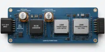
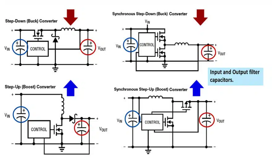
DC-DC Power Conversion in Switched Mode Power Supplies

Figure 1 shows how capacitors are used in voltage regulators:

Figure 1: Capacitor application in Buck and Boost converters; source: KYOCERA AVX

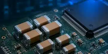
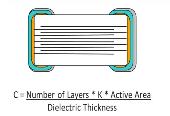
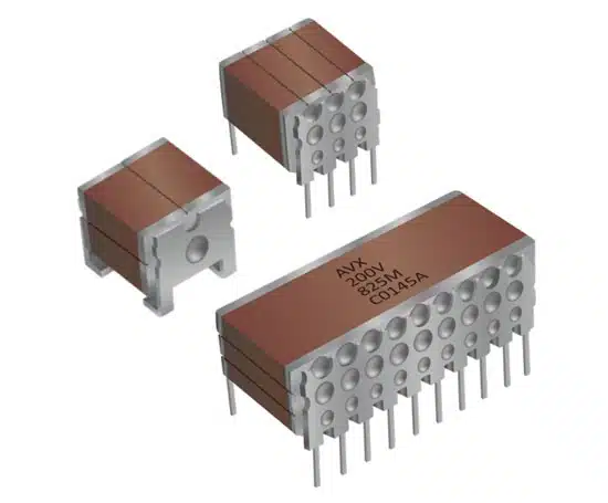
MLCC Ceramic Capacitors

Multilayer ceramic capacitors, also known as MLCCs, are the capacitors of choice in applications requiring small capacitances and are constructed using alternating layers of ceramic and metal. MLCCs are suitable for modern high-frequency applications due to their ultra-low equivalent series resistance (ESR). MLCCs can be broadly classified into two types:

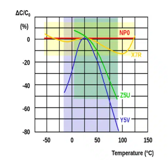
  • Class 1: NPO/COG materials (Temperature compensation MLCC)
  • Class 2: X7R, X5R, X7S, X6S,Y5V materials (High dielectric constant MLCC)

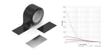
The main difference between the two is that the capacitance of Class 2 varies with changes in the measurement voltage and temperature, while there is no capacitance variation in Class 1. Figures 2-4 and Table 1 show some of the most important characteristics of MLCCs:

Figure 2: MLCC construction. Alternate layers of electrodes and dielectric materials effectively create multiple parallel capacitors in a single device to increase the capacitance; source: KYOCERA AVX
Figure 4: Voltage coefficient of capacitance – Capacitance decrease with applied voltage on different ceramic dielectric class materials; source: KYOCERA AVX
Figure 3: Temperature coefficient of capacitance (TCC) of the most common ceramic dielectric types; source: KYOCERA AVX
Table 1: Characteristics of MLCCs; source: KYOCERA AVX

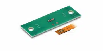
Integrating Capacitors into Electronic Circuits: Series vs. Parallel

MLCCs can be integrated into electronic circuits in two ways: series and parallel connections. Figures 5, 6, and 7 show how to achieve this.

Figure 5: An example of capacitors in parallel module to increase the equivalent capacitance; source: KYOCERA AVX
Figure 6: Using capacitors in series to meet customers’ voltage rating requirements; source: KYOCERA AVX
Figure 7: Flexisafe – Using ceramic capacitors in series to ensure failsafe capability; source: KYOCERA AVX

Spice Simulation Software

KYOCERA AVX offers the SpiCALCI 10 (the latest version of its SpiCALCI software), which is an engineering tool that simulates performance characteristics and parameters for its advanced switch-mode power supply (SMPS) multilayer ceramic capacitors (MLCCs).

KYOCERA AVX created this tool to help electrical design engineers select a part that will best satisfy their application criteria. KYOCERA AVX’s SpiCalci10 software allows electrical
design engineers to predict critical parameters, such as self-resonant frequency, ESR, ESL, and phase angle, for a given ambient temperature, temperature rise, and operational frequency. Moreover, designers can adjust the variables numerically, via a button slide, to model important capacitor characteristics, such as ripple current, ripple voltage, and internal temperature.

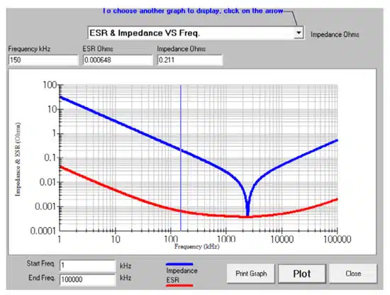
The software also helps to generate interactive graphs for further analysis of ESR and impedance vs. frequency, temperature rise vs. current, maximum current vs. frequency, maximum ripple voltage vs. frequency, phase angle vs. frequency, and capacitance changes with DC bias. The numerical data can be imported to SPICE simulation software, and the graphs can be saved and printed for presentation or sharing.

Key parameters for designing circuits with MLCCs:

  • Allowable ripple current and ripple voltage
  • ESR compared to other passive components
  • Temperature rise
  • Thermal resistance

Maximum Allowable AC Ripple Current: In most electronic devices, the DC current signal applied to a circuit has an AC portion. This AC portion is referred to as the ripple current. The AC ripple current causes power dissipation and heating in capacitors. The power dissipated by a capacitor is a function of the ripple current and its equivalent series resistance (ESR). Heating in ceramic capacitors causes thermal gradients, which could result in degradation and cracking. Thus, ripple current capability is one of the key parameters to consider when selecting a capacitor for a specific application.

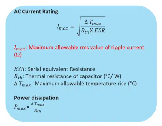
Heat Generation Characteristics of MLCCs: When ripple current (AC) flows through a capacitor, the resistor element generates heat, and the temperature rises. However, since the
MLCC offers an extremely small equivalent series resistance (ESR), the heat rise is minimal, and its ripple resistance capability is excellent. Many manufacturers specify the surface temperature of the component to be below 20 °C. Figure 8 shows a mathematical formula for calculating the maximum allowable ripple current of MLCCs:

.Figure 8: Formulas for calculating the maximum allowable ripple current and power dissipation in an MLCC
Figure 9: KYOCERA AVX SpiCalCi10 simulation of maximum current vs. frequency; source: KYOCERA AVX

Ripple Voltage (RMS) For Ceramic Capacitors: A simple formula for calculating the maximum ripple voltage of a ceramic capacitor is:
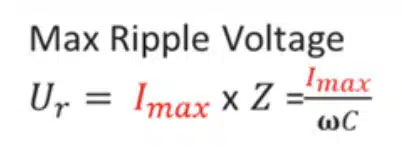
where:

  • Ur = maximum ripple voltage (rms)
  • Imax = maximum allowable rms value of ripple current
  • Z = impedance
  • ω = 2πf
  • C = capacitance
Figure 10: KYOCERA AVX SpiCalCi10 simulation of maximum ripple voltage vs. frequency; source: KYOCERA AVX

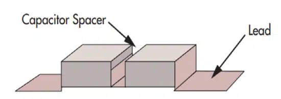
ESR Constitution: Because practical capacitors are non-ideal components, they offer some level of resistance within their constitution. When integrated in series in electronic circuits, the equivalent series resistance (ESR) is an essential parameter. Alongside the capacitance, the ESR defines a time constant for charging or discharging the capacitor and how quickly it reacts to variations in voltage, current, and ripple. Figure 11 shows the ESR constitution of a ceramic capacitor.

Figure 11: A formula for calculating the ESR of the ceramic MLCC capacitor

where:

  • tan δ = dissipation factor of the capacitor
  • tan δ0 = dissipation factor of the dielectric
  • C = capacitance
  • Rs = series resistance
  • ESR = equivalent series resistance
Figure 12: KYOCERA AVX SpiCalCi10 simulation of ESR and impedance vs. frequency; source: KYOCERA AVX

Maximum Temperature Rise: As previously mentioned, when ripple current passes through a capacitor, power is dissipated in the form of heat, resulting in temperature rise (self-heating). Other factors include dielectric losses and the temperature of the surroundings (ambient temperature).

Figure 13: KYOCERA AVX SpiCalci10 simulation of temperature rise vs. applied current; source: KYOCERA AVX

All of these factors compound to affect the temperature of an MLCC. Since MLCCs are dependent on temperature and not current, variations in the temperature will determine the maximum ripple current. The maximum temperature rise of ceramic capacitors is usually limited to 50°C to prevent damage to the component (cracking) due to thermal gradients.

For example, take a X7R MLCC with a temperature range from (-55°C to 125°C). When the circuit is operating at +25°C, the MLCC can handle enough current until the part has heated up to 125°C.

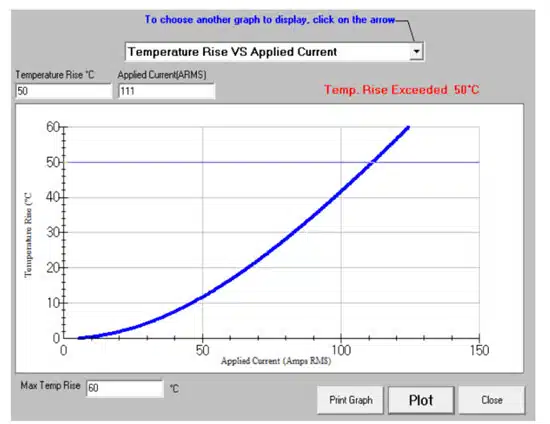
However, when the same circuit is at 100°C, the ripple current would be less as there is a lower temperature differential. The KYOCERA AVX SpiCalci10 simulation below shows temperature rise vs. applied current with the following parameters:

  • Imax = 111A(rms)
  • Irms = 66.3A(rms)
  • ΔTmax = 50°C
  • ΔT = 20°C

Key Parameters for Designing Ceramic Capacitors in SMPS Circuits

Ripple Voltage (RMS) for Ceramic Capacitors

Figure 14: Smoothing/snubbing applications of ceramic capacitors; source: KYOCERA AVX

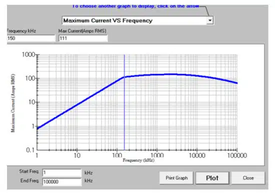
The maximum ripple current voltage in the application shall not exceed the maximum ratings of the capacitor. KYOCERA AVX SpiCalCi10 simulation of maximum ripple voltage vs. frequency as shown in Figure 10. can be used to assess capability of the selected part versus the real application requirements at desired frequency range.

Thermal Resistance

The thermal resistance (Rth) between a capacitor and the environment is a function of the airflow over the capacitor, the surface area of the capacitor, and any heat sinking of the capacitor. To specify the most conservative (lowest) values of ripple current capability, the thermal resistance of the MLCC is measured under still air with no heat sinking at 25°C ambient temperature.

Rth will be different for each case size as it depends on both the internal construction of the capacitor (pellet size and thermal paths) and the external surface area. Recall that thermal gradients caused by the heat generated by ripple currents can crack the ceramic chip. Electrode plates act as heat sinks, and capacitors with a high number of plates release heat from ceramic blocks more easily than components of the same size but with fewer plates.

Conclusion

Internal heating within ceramic capacitors affects the performance of many electronic circuits. In these capacitors, the maximum ripple current is determined by the temperature characteristics of the component.

Exceeding the ripple current rating of a ceramic capacitor can significantly affect its performance. The coefficients of thermal resistance for ceramic capacitors of a given chip size vary due to differences in the number of electrode plates.

Heating in ceramic capacitors causes thermal gradients that could result in physical damage such as cracking. The maximum temperature rise in ceramic capacitors is usually limited to 50°C to prevent cracking.

Related

Source: KYOCERA AVX

Recent Posts

RF Inductors: Selection and Design Challenges for High-Frequency Circuits

10.11.2025
26

Transformer Safety IEC 61558 Standard

7.11.2025
12

ESR of Capacitors, Measurements and Applications

7.11.2025
49

3-Phase EMI Filter Design, Simulation, Calculation and Test

6.11.2025
54

KYOCERA AVX Releases Antenna for Iridium Satellite IoT Applications

6.11.2025
13
Image credit: Samtec

How to Match the Right Connector with Protocol Requirements

6.11.2025
14

Smoltek CNF-MIM Capacitors Pass 1,000h Reliability Test

6.11.2025
12

Capacitor Lead Times: October 2025

6.11.2025
68

Paumanok Unveils Aluminum Capacitor Foils World Markets Study 2025-2030

6.11.2025
15

Upcoming Events

Nov 12
11:00 - 12:00 CET

PCB Design: Impedance is for everyone!

Nov 12
November 12 @ 12:00 - November 13 @ 14:15 EST

Microelectronic Packaging Failure Modes and Analysis

Nov 13
11:00 - 11:30 CET

DC/DC Converters in Automotive Applications

View Calendar

Popular Posts

  • Buck Converter Design and Calculation

    0 shares
    Share 0 Tweet 0
  • Boost Converter Design and Calculation

    0 shares
    Share 0 Tweet 0
  • LLC Resonant Converter Design and Calculation

    0 shares
    Share 0 Tweet 0
  • Flyback Converter Design and Calculation

    0 shares
    Share 0 Tweet 0
  • Ripple Current and its Effects on the Performance of Capacitors

    3 shares
    Share 3 Tweet 0
  • MLCC and Ceramic Capacitors

    0 shares
    Share 0 Tweet 0
  • Dual Active Bridge (DAB) Topology

    0 shares
    Share 0 Tweet 0
  • SEPIC Converter Design and Calculation

    0 shares
    Share 0 Tweet 0
  • What is a Dielectric Constant and DF of Plastic Materials?

    4 shares
    Share 4 Tweet 0
  • What Electronics Engineer Needs to Know About Passive Low Pass Filters

    0 shares
    Share 0 Tweet 0

Newsletter Subscription


Passive Components Blog

© EPCI - Leading Passive Components Educational and Information Site

  • Home
  • Privacy Policy
  • EPCI Membership & Advertisement
  • About

No Result
View All Result
  • Home
  • Knowledge Blog
  • PCNS

© EPCI - Leading Passive Components Educational and Information Site

This website uses cookies. By continuing to use this website you are giving consent to cookies being used. Visit our Privacy and Cookie Policy.
Go to mobile version