







Passive Components Blog
No Result
View All Result
  • Home
  • NewsFilter
    • All
    • Aerospace & Defence
    • Antenna
    • Applications
    • Automotive
    • Capacitors
    • Circuit Protection Devices
    • electro-mechanical news
    • Filters
    • Fuses
    • Inductors
    • Industrial
    • Integrated Passives
    • inter-connect news
    • Market & Supply Chain
    • Market Insights
    • Medical
    • Modelling and Simulation
    • New Materials & Supply
    • New Technologies
    • Non-linear Passives
    • Oscillators
    • Passive Sensors News
    • Resistors
    • RF & Microwave
    • Telecommunication
    • Weekly Digest

    LeanBOM: Practical Cross‑Technology Capacitor Search by Real Working Conditions

    In the Age of AI, Every Watt Counts: Implications for Components

    Stackpole Extends Resistance Range of 2512 High‑Power Current Sense Resistors

    Wk 27 Electronics Supply Chain Digest

    Littelfuse Announced TVS Diodes for 48 V Automotive Systems

    Spectrum Controls Joins Modelithics Program to Offer High‑Fidelity RF Models for Resistors, Attenuators and Terminations

    RF Filters and Passive Components Enabling the 7 Missile RF Subsystems

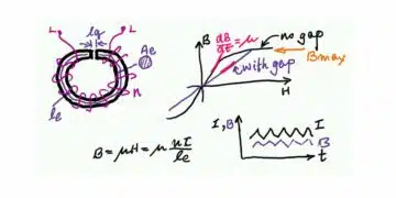
    Ferrite versus Nanocrystalline Power Inductor Cores: Turns, Gap and Size

    YAGEO Presents NANOMET Soft Magnetic Cores for High‑Density Power Conversion

    Trending Tags

    • Ripple Current
    • RF
    • Leakage Current
    • Tantalum vs Ceramic
    • Snubber
    • Low ESR
    • Feedthrough
    • Derating
    • Dielectric Constant
    • New Products
    • Market Reports
  • VideoFilter
    • All
    • Antenna videos
    • Capacitor videos
    • Circuit Protection Video
    • Filter videos
    • Fuse videos
    • Inductor videos
    • Inter-Connect Video
    • Non-linear passives videos
    • Oscillator videos
    • Passive sensors videos
    • Resistor videos

    Ferrite versus Nanocrystalline Power Inductor Cores: Turns, Gap and Size

    KYOCERA AVX Presents Antenna Integrator Studio Tutorial for Antenna Placement and RF Design

    Power Design Simulation Tools for Faster Inductor Selection and Loss Optimization

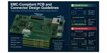
    EMC‑Compliant PCB and Connector Design Guidelines

    Why Isolated DC/DC Power Supplies Fail Late, Würth Elektronik Podcast

    Designing 800 V DC EMC Filters: Calculation, Simulation and Measurement

    Current Sense Transformer Datasheet and Design‑in Guide

    Designing a USB Type‑C Flyback Planar Transformer with Frenetic’s Planar Tool

    Magnetics Design in High‑Frequency GaN Converters

    Trending Tags

    • Capacitors explained
    • Inductors explained
    • Resistors explained
    • Filters explained
    • Application Video Guidelines
    • EMC
    • New Products
    • Ripple Current
    • Simulation
    • Tantalum vs Ceramic
  • Knowledge Blog
  • Dossiers
    • AI Hardware Dossier
    • Power Converter Dossier
    • Automotive Dossier
    • Capacitor Dossier
    • Resistor Dossier
    • Inductor Dossier
    • Circuit Protection Dossier
  • Suppliers
    • Who is Who
  • PCNS
    • PCNS 2025
    • PCNS 2023
    • PCNS 2021
    • PCNS 2019
    • PCNS 2017
  • Events
  • Home
  • NewsFilter
    • All
    • Aerospace & Defence
    • Antenna
    • Applications
    • Automotive
    • Capacitors
    • Circuit Protection Devices
    • electro-mechanical news
    • Filters
    • Fuses
    • Inductors
    • Industrial
    • Integrated Passives
    • inter-connect news
    • Market & Supply Chain
    • Market Insights
    • Medical
    • Modelling and Simulation
    • New Materials & Supply
    • New Technologies
    • Non-linear Passives
    • Oscillators
    • Passive Sensors News
    • Resistors
    • RF & Microwave
    • Telecommunication
    • Weekly Digest

    LeanBOM: Practical Cross‑Technology Capacitor Search by Real Working Conditions

    In the Age of AI, Every Watt Counts: Implications for Components

    Stackpole Extends Resistance Range of 2512 High‑Power Current Sense Resistors

    Wk 27 Electronics Supply Chain Digest

    Littelfuse Announced TVS Diodes for 48 V Automotive Systems

    Spectrum Controls Joins Modelithics Program to Offer High‑Fidelity RF Models for Resistors, Attenuators and Terminations

    RF Filters and Passive Components Enabling the 7 Missile RF Subsystems

    Ferrite versus Nanocrystalline Power Inductor Cores: Turns, Gap and Size

    YAGEO Presents NANOMET Soft Magnetic Cores for High‑Density Power Conversion

    Trending Tags

    • Ripple Current
    • RF
    • Leakage Current
    • Tantalum vs Ceramic
    • Snubber
    • Low ESR
    • Feedthrough
    • Derating
    • Dielectric Constant
    • New Products
    • Market Reports
  • VideoFilter
    • All
    • Antenna videos
    • Capacitor videos
    • Circuit Protection Video
    • Filter videos
    • Fuse videos
    • Inductor videos
    • Inter-Connect Video
    • Non-linear passives videos
    • Oscillator videos
    • Passive sensors videos
    • Resistor videos

    Ferrite versus Nanocrystalline Power Inductor Cores: Turns, Gap and Size

    KYOCERA AVX Presents Antenna Integrator Studio Tutorial for Antenna Placement and RF Design

    Power Design Simulation Tools for Faster Inductor Selection and Loss Optimization

    EMC‑Compliant PCB and Connector Design Guidelines

    Why Isolated DC/DC Power Supplies Fail Late, Würth Elektronik Podcast

    Designing 800 V DC EMC Filters: Calculation, Simulation and Measurement

    Current Sense Transformer Datasheet and Design‑in Guide

    Designing a USB Type‑C Flyback Planar Transformer with Frenetic’s Planar Tool

    Magnetics Design in High‑Frequency GaN Converters

    Trending Tags

    • Capacitors explained
    • Inductors explained
    • Resistors explained
    • Filters explained
    • Application Video Guidelines
    • EMC
    • New Products
    • Ripple Current
    • Simulation
    • Tantalum vs Ceramic
  • Knowledge Blog
  • Dossiers
    • AI Hardware Dossier
    • Power Converter Dossier
    • Automotive Dossier
    • Capacitor Dossier
    • Resistor Dossier
    • Inductor Dossier
    • Circuit Protection Dossier
  • Suppliers
    • Who is Who
  • PCNS
    • PCNS 2025
    • PCNS 2023
    • PCNS 2021
    • PCNS 2019
    • PCNS 2017
  • Events
No Result
View All Result
Passive Components Blog
No Result
View All Result

Circular Connectors Coding

26.11.2025
Reading Time: 8 mins read
A A

This post provides a comprehensive technical explanation of connector coding, focusing on the industry-standard M12 and its compact variant M8, complete with specifications, usage cases, and engineering context.

Key Takeaways

  • This article explains connector coding with a focus on M12 and M8 connectors, emphasizing their importance in industrial automation.
  • Connector coding prevents mismating, ensures reliability, saves time, and enhances safety during installations and maintenance.
  • M12 connectors offer various coding types for different applications, while M8 connectors are suitable for space-constrained environments.
  • Coding benefits include reliable communication in industrial networks and protection against environmental factors.
  • Selecting the correct connector involves considering voltage, signal type, mechanical constraints, and environmental requirements.

Introduction
Circular connectors like M12 and M8 are fundamental in industrial automation, robotics, and transportation. Coding systems ensure safety, compatibility, and reliability by preventing mismating and supporting quick, error-free installation.

RelatedPosts

LeanBOM: Practical Cross‑Technology Capacitor Search by Real Working Conditions

In the Age of AI, Every Watt Counts: Implications for Components

Stackpole Extends Resistance Range of 2512 High‑Power Current Sense Resistors

Why Connector Coding Matters

Connector coding is essential for daily operations involving installation, maintenance, and upgrades. Each time a connector is removed or replaced, incorrect mating can cause failures, downtime, or hazards. Coding addresses this by:

  • Preventing mismating: Unique pin/socket/keying layouts only allow correct matching.
  • Ensuring reliability: Mechanical features align connectors accurately before locking.
  • Saving time: Field technicians can connect devices safely, reducing installation errors.
  • Enhancing safety: Cross-connections, short circuits, and voltage errors are avoided.

Coding is vital in all industries that require error-free signal, data, and power transmission.

M12 Connector Coding – Technical Overview

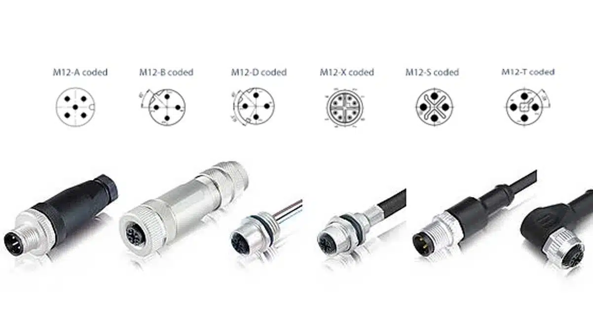
M12 connectors have become a leading choice for automation due to their compact size, durability, and broad coding selection. The key coding types and their major properties are outlined below:

TypeCurrentVoltageProtectionContactsApplications
A-coded1.5–8A30–250VACIP67/68/69K3–12Sensors, CAN, DeviceNet, DC Power
B-coded4A60–250VACIP67/684–5PROFIBUS DP
D-coded4A250VACIP674Ethernet, EtherCAT, PROFINET, Sercos
X-coded0.5A50VAC/60VDCIP678High-Speed Ethernet up to 10 Gbit/s
S-coded12A630VACIP673+PEAC Power Supply
K-coded12A630VACIP674+PEAC Power Supply (higher pole count)
L-coded16A63VDCIP674–FEDC Power Supply, PROFINET
T-coded12A60VDCIP674DC Power Supply
US-coded4A250VACIP673–5Signal

M8 Connector Coding – Technical Overview

M8 connectors are ideal for space-constrained environments and miniaturized machinery. Their coding types match the diversity of industrial requirements for signal, data, and low-power applications.
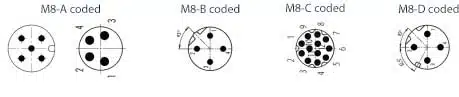
TypeCurrentVoltageProtectionContactsApplications
A-coded1.5–4A30–60VACIP65/67/68/69K3–8Power, Signal, CAN, DeviceNet
B-coded3A30–60VACIP67/68/69K5PROFIBUS DP
C-coded1A30–32VACIP6712Power, Signal
D-coded1.5–4A50–63VACIP674Ethernet, PROFINET

Coding Benefits & Use Cases

  • Fieldbus and Ethernet: M12 D-coded and X-coded ensure communication reliability for PROFIBUS, PROFINET, EtherCAT, and high-speed Ethernet networks up to 10 Gbit/s.
  • Power separation: Codings like T, L, S, K in M12 and A, C in M8 ensure proper voltage levels and protect sensitive electronics.
  • Industrial sensors: M8 A-coded and M12 A-coded widely used for field device power and signal connections.
  • Harsh environments: IP67–IP69K protection maintains integrity against dust, water, and vibration.

Color coding and mechanical keying in these connectors facilitate easy, error-proof deployment by visual and tactile feedback, critical for technicians working under time constraints.

Practical Engineering Selection

When specifying a connector, engineers should reference the coding charts above and consider:

  • Voltage and current levels (match rating to application)
  • Signal/data type (fieldbus vs. power delivery)
  • Mechanical constraints (pin count, housing size)
  • Environmental requirements (IP protection, temperature)

Correct coding selection prevents device damage, system errors, and future-proofs installations for expansions or upgrades.

Conclusion

Connector coding is a subtle but crucial part of system engineering in industrial automation. By employing standardized coding schemes—especially in M12 and M8 connectors—engineers gain robust, safe, and reliable interconnect solutions. Coding ensures error-free installation, operational safety, and compatibility for applications as diverse as high-speed communication, AC/DC power distribution, and miniature sensor networks. Adhering to appropriate coding practices is essential for long-lasting, efficient operations in all automation and control systems.

FAQ – Coding in Circular Connectors

Why do circular connectors have different codings?

Circular connectors use coding systems to prevent mismatching, guarantee correct mating, and ensure safe, reliable connections in industrial and automation applications.

What is a coded connector?

A coded connector features unique pin, socket, and mechanical keying layouts to ensure that only the correct plug fits the correct socket, preventing error-prone connections.

What are the main types of coding in circular connectors?

A- and B-coding support sensor connections and data lines by ensuring correct orientation and application-specific compatibility, thus reducing the risk of signal interference or equipment damage.

Can M12 connectors be used for both power and data?

Yes, M12 connectors are available in coding types suitable for both power (e.g., S, K, L, T) and data (e.g., D, X), letting engineers safely combine different transmission needs within one robust format.

What is the difference between M8 and M12 coding?

M8 connectors are smaller and ideal for compact applications but offer fewer coding types than M12. M12 offers a broader variety of codings for high-power, data, and sensor applications.

What does A-, B-, D-, and X-coding mean for M12 connectors?

A-coding is used for sensors and DC power; B-coding for PROFIBUS; D-coding for Ethernet up to 100 Mbit/s; X-coding for high-speed Ethernet up to 10 Gbit/s.

Related

Source: binder

Recent Posts

Molex Unveils Automotive Ethernet Connectors for Next‑Gen SDV Architectures

2.7.2026
42

binder Prints Electronics on 3D Components Connector Surface

1.7.2026
21

EMC‑Compliant PCB and Connector Design Guidelines

22.6.2026
104

Hirose Releases Ultra‑low Profile FPC‑to‑board Connector

17.6.2026
41

Molex Expanded AirBorn SInergy Hybrid Connectors with 25 A Power Modules

16.6.2026
40

Hirose Releases 0.5 mm Floating Board-to-Board Connector for EV Powertrain Designs

15.6.2026
25

Hirose Expands Compact High‑Voltage EV connectors

21.5.2026
57

YAGEO Releases Compact RJ45 Connector for Multi‑Gigabit Ethernet

18.5.2026
55

Binder Hybrid Connector Simplifies One Cable Automation

13.5.2026
47

Upcoming Events

Jul 14
16:00 - 17:00 CEST

EMC Design Essentials: Mastering Varistors and Common Mode Chokes

Jul 21
16:00 - 17:00 CEST

Safety by design: X and Y Interference suppression capacitors for power line filters

Jul 28
8:00 - 11:00 CEST

Post Procurement Testing of EEE Components for LEO Space Applications

View Calendar

Popular Posts

  • Boost Converter Design and Calculation

    0 shares
    Share 0 Tweet 0
  • Buck Converter Design and Calculation

    0 shares
    Share 0 Tweet 0
  • Flyback Converter Design and Calculation

    0 shares
    Share 0 Tweet 0
  • LLC Resonant Converter Design and Calculation

    0 shares
    Share 0 Tweet 0
  • YAGEO Announces July 2026 Capacitor Price Increase

    0 shares
    Share 0 Tweet 0
  • MLCC and Ceramic Capacitors

    0 shares
    Share 0 Tweet 0
  • Earthing Systems and IEC Classification Explained

    0 shares
    Share 0 Tweet 0
  • Nvidia Vera Rubin: Why One AI Rack Needs So Many More MLCC Capacitors

    0 shares
    Share 0 Tweet 0
  • MLCCs in the Age of AI: Q2 2026 Market Tightness

    0 shares
    Share 0 Tweet 0
  • Dual Active Bridge (DAB) Topology

    0 shares
    Share 0 Tweet 0

Newsletter Subscription


Passive Components Blog

© EPCI - Leading Passive Components Educational and Information Site

  • Home
  • Privacy Policy
  • EPCI Membership & Advertisement
  • About

No Result
View All Result
  • Home
  • Knowledge Blog
  • Dossiers
  • PCNS

© EPCI - Leading Passive Components Educational and Information Site

This website uses cookies. By continuing to use this website you are giving consent to cookies being used. Visit our Privacy and Cookie Policy.
Go to mobile version