Passive Components Blog
No Result
View All Result
  • Home
  • NewsFilter
    • All
    • Aerospace & Defence
    • Antenna
    • Applications
    • Automotive
    • Capacitors
    • Circuit Protection Devices
    • electro-mechanical news
    • Filters
    • Fuses
    • Inductors
    • Industrial
    • Integrated Passives
    • inter-connect news
    • Market & Supply Chain
    • Market Insights
    • Medical
    • Modelling and Simulation
    • New Materials & Supply
    • New Technologies
    • Non-linear Passives
    • Oscillators
    • Passive Sensors News
    • Resistors
    • RF & Microwave
    • Telecommunication
    • Weekly Digest

    Silicon Capacitors Market: Shaping the Foundation for Next-Gen Miniaturization Electronics

    YAGEO Releases Compact Coupled Inductors for High-Density VR Designs

    Enhancing Energy Density in Nanocomposite Dielectric Capacitors

    Advances in the Environmental Performance of Polymer Capacitors

    Vishay Releases DLA Tantalum Polymer Capacitors for Military and Aerospace

    Vishay Expanded Inductor Portfolio With More Than 2000 Stock Items 

    Paumanok Releases Capacitor Foils Market Report 2025-2030

    Modelithics Welcomes CapV as a Sponsoring MVP

    Wk 40 Electronics Supply Chain Digest

    Trending Tags

    • Ripple Current
    • RF
    • Leakage Current
    • Tantalum vs Ceramic
    • Snubber
    • Low ESR
    • Feedthrough
    • Derating
    • Dielectric Constant
    • New Products
    • Market Reports
  • VideoFilter
    • All
    • Antenna videos
    • Capacitor videos
    • Circuit Protection Video
    • Filter videos
    • Fuse videos
    • Inductor videos
    • Inter-Connect Video
    • Non-linear passives videos
    • Oscillator videos
    • Passive sensors videos
    • Resistor videos

    Connector PCB Design Challenges

    Efficient Power Converters: Duty Cycle vs Conduction Losses

    Ripple Steering in Coupled Inductors: SEPIC Case

    SEPIC Converter with Coupled and Uncoupled Inductors

    Coupled Inductors in SEPIC versus Flyback Converters

    Non-Linear MLCC Class II Capacitor Measurements Challenges

    Percolation Phenomenon and Reliability of Molded Power Inductors in DC/DC converters

    Root Causes and Effects of DC Bias and AC in Ceramic Capacitors

    How to Calculate the Output Capacitor for a Switching Power Supply

    Trending Tags

    • Capacitors explained
    • Inductors explained
    • Resistors explained
    • Filters explained
    • Application Video Guidelines
    • EMC
    • New Products
    • Ripple Current
    • Simulation
    • Tantalum vs Ceramic
  • Knowledge Blog
  • Suppliers
    • Who is Who
  • Events
No Result
View All Result
Passive Components Blog
No Result
View All Result

Connector Temperature and Current Ratings Challenges

13.1.2023
Reading Time: 3 mins read
A A

Thermal management and temperature derating have always been something that designers have had to plan for to keep their products safe. Temperature and power are closely linked, especially when it comes to connectors. This Samtec article discusses connector temperature and current rating challenges.

The Resistance

RelatedPosts

Samtec Agreed with Molex Second-Source License on High-Speed Interconnects for Data Centers

Best Practices for Cable Management in High-Speed and High-Density Systems

Samtec Releases 800-Position High-Performance Array Connectors  

Every electrical circuit has resistance. The value may be small, but when passing power through that circuit, any resistance causes some of the energy to be converted into heat. With enough power, this can cause a rise in the temperature of the terminal, and therefore everything else around it.

For this reason, it is important to understand how much heat is generated. In common with many connector manufacturers, In the example below Samtec publishes a temperature derating chart, in particular for power connectors. Here is an example, taken from the popular mPOWER® series of power connectors. This chart on Figure 1. shows the maximum power rating for contacts for a particular ambient temperature.

Figure 1. Connector derating chart example of power connectors; source: Samtec

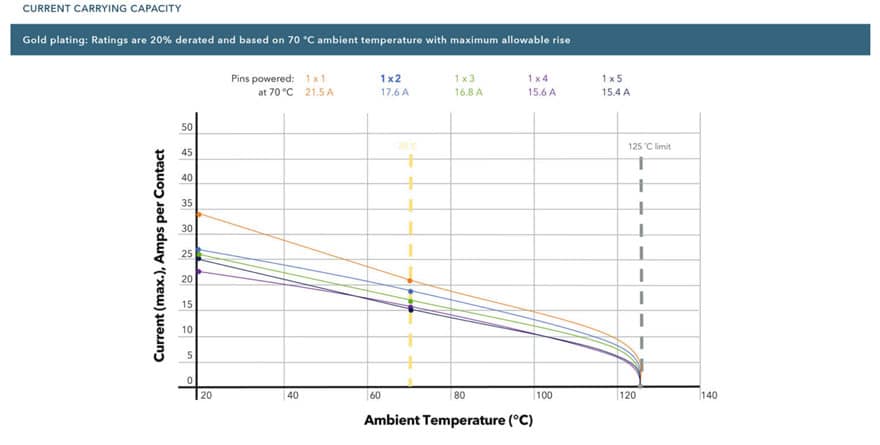
In the example on Figure 1. shown here, we can see that an ambient temperature of 70°C requires that we reduce the current passing through the contact by 20%. Placing this information into a hypothetical real-world installation, we can see that external conditions play an important role in the performance of connectors. 

We also need to consider the published operating temperature of the connector itself. This will often be limited by the materials used in the connector’s design, in particular the plastic used for the insulator. In our hypothetical example, the operating temperature range of the connector might be 125°C, typical for a connector fitted with gold-plated contacts. There are also connector types with tin-plate contact finishes as a more cost-effective option. However, it is important to note that the operating temperature for tin-plated contacts is lower. 

Solving the Temperature Problem

There are several solutions to the problem of temperature and current ratings. The simplest approach is to use a connector with larger contacts. One of the key factors governing the current rating of an electrical terminal is its mass. A larger terminal with more material should have a lower resistance and be able to carry more power. However, as we are trying to find solutions for the compact designs of the future, a larger connector is not always convenient.

Another way to solve the problem is to use a connector with a larger pitch. Pitch is the term used to describe the distance between terminals within electrical and electronic components. A greater pitch will aid in the dissipation of heat, which should lead to a reduced temperature rise for a given current. However, this is also will result in a larger connector, which does not solve our design problem.

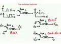
The thoughtful approach is to consider the contacts themselves. Conventional designs comprise a fixed male contact that is inserted into a socket or female. The mating area of the female terminal is split or bifurcated, and the two parts provide a constant force to ensure electrical continuity. The actual area of contact between the two terminals is small. However, alternative contact designs allow greater performance.

Related

Source: Samtec

Recent Posts

Connector PCB Design Challenges

3.10.2025
28

Efficient Power Converters: Duty Cycle vs Conduction Losses

29.9.2025
33

DigiKey Announces Back to School Giveaway to Empower Tomorrow’s Innovators

27.8.2025
13

Würth Elektronik Expands MagI³C with Variable Step-Down Modules

30.7.2025
34

Switched Capacitor Converter Explained

28.7.2025
118

DigiKey Offers Zephyr Operating System Workshop and Training Videos

6.6.2025
21

How to design a 60W Flyback Transformer

12.5.2025
173

Würth Elektronik Offers New Power Supplies Development Kit

29.4.2025
55

Non-Magnetic Interconnects

23.4.2025
27

DigiKey Announces Sponsorship of KiCad to Support Open-Source EDA Development

9.4.2025
17

Upcoming Events

Oct 14
16:00 - 17:00 CEST

Smart Sensors, Smarter AI: Building Reliable Edge Systems

Oct 17
12:00 - 14:00 EDT

External Visual Inspection per MIL-STD-883 TM 2009

Oct 20
October 20 - October 23

Digital WE Days 2025 – Virtual Conference

Oct 21
October 21 @ 12:00 - October 23 @ 14:15 EDT

Space and Military Standards for Hybrids and RF Microwave Modules

Oct 28
8:00 - 15:00 CET

Power Up Your Design: SN6507 and the Ready-to-Use Development Kit

View Calendar

Popular Posts

  • Buck Converter Design and Calculation

    0 shares
    Share 0 Tweet 0
  • Boost Converter Design and Calculation

    0 shares
    Share 0 Tweet 0
  • Flyback Converter Design and Calculation

    0 shares
    Share 0 Tweet 0
  • LLC Resonant Converter Design and Calculation

    0 shares
    Share 0 Tweet 0
  • What is a Dielectric Constant and DF of Plastic Materials?

    4 shares
    Share 4 Tweet 0
  • SEPIC Converter Design and Calculation

    0 shares
    Share 0 Tweet 0
  • Dual Active Bridge (DAB) Topology Explained

    0 shares
    Share 0 Tweet 0
  • Ripple Current and its Effects on the Performance of Capacitors

    3 shares
    Share 3 Tweet 0
  • Flying Capacitors Explained

    0 shares
    Share 0 Tweet 0
  • MLCC and Ceramic Capacitors

    0 shares
    Share 0 Tweet 0

Newsletter Subscription


Passive Components Blog

© EPCI - Leading Passive Components Educational and Information Site

  • Home
  • Privacy Policy
  • EPCI Membership & Advertisement
  • About

No Result
View All Result
  • Home
  • Knowledge Blog
  • Premium Suppliers

© EPCI - Leading Passive Components Educational and Information Site

This website uses cookies. By continuing to use this website you are giving consent to cookies being used. Visit our Privacy and Cookie Policy.
Go to mobile version