Passive Components Blog
No Result
View All Result
  • Home
  • NewsFilter
    • All
    • Aerospace & Defence
    • Antenna
    • Applications
    • Automotive
    • Capacitors
    • Circuit Protection Devices
    • electro-mechanical news
    • Filters
    • Fuses
    • Inductors
    • Industrial
    • Integrated Passives
    • inter-connect news
    • Market & Supply Chain
    • Market Insights
    • Medical
    • Modelling and Simulation
    • New Materials & Supply
    • New Technologies
    • Non-linear Passives
    • Oscillators
    • Passive Sensors News
    • Resistors
    • RF & Microwave
    • Telecommunication
    • Weekly Digest

    July 2025 ECST Components Survey Continue with Strong Sales Sentiment

    SCHURTER Releases Chip Fuse for ATEX and Precision Applications

    SCHURTER Introduces Reliable Arc-Free Switching Technology

    Additive Manufacturing of Mn-Zn Ferrite Planar Inductors

    Evaluation and Modeling of Supercapacitors for Reliability of Lifetime Predictions

    Hirose Releases High Current Vibration-Resistant Connectors

    Researchers Presents High-Performance Carbon-Based Supercapacitors

    Hirose Launches World’s Lowest Profile and Narrowest Pitch FPC Connector

    Modelithics Announces v25.5 of the COMPLETE+3D Library for Ansys HFSS

    Trending Tags

    • Ripple Current
    • RF
    • Leakage Current
    • Tantalum vs Ceramic
    • Snubber
    • Low ESR
    • Feedthrough
    • Derating
    • Dielectric Constant
    • New Products
    • Market Reports
  • VideoFilter
    • All
    • Antenna videos
    • Capacitor videos
    • Circuit Protection Video
    • Filter videos
    • Fuse videos
    • Inductor videos
    • Inter-Connect Video
    • Non-linear passives videos
    • Oscillator videos
    • Passive sensors videos
    • Resistor videos

    Switched Capacitor Converter Explained

    Understanding Inductor Dot Markings and Their Application in LTspice

    Accelerating Full Bridge LLC Resonant Converter Design with Frenetic AI

    Understanding Switched Capacitor Converters

    Coupled Inductors Circuit Model and Examples of its Applications

    Inductor Resonances and its Impact to EMI

    Highly Reliable Flex Rigid PCBs, Würth Elektronik Webinar

    Causes of Oscillations in Flyback Converters

    How to design a 60W Flyback Transformer

    Trending Tags

    • Capacitors explained
    • Inductors explained
    • Resistors explained
    • Filters explained
    • Application Video Guidelines
    • EMC
    • New Products
    • Ripple Current
    • Simulation
    • Tantalum vs Ceramic
  • Knowledge Blog
  • Suppliers
    • Who is Who
  • Events
No Result
View All Result
Passive Components Blog
No Result
View All Result

Contact Force and Mating Wear/Durability

8.9.2021
Reading Time: 2 mins read
A A

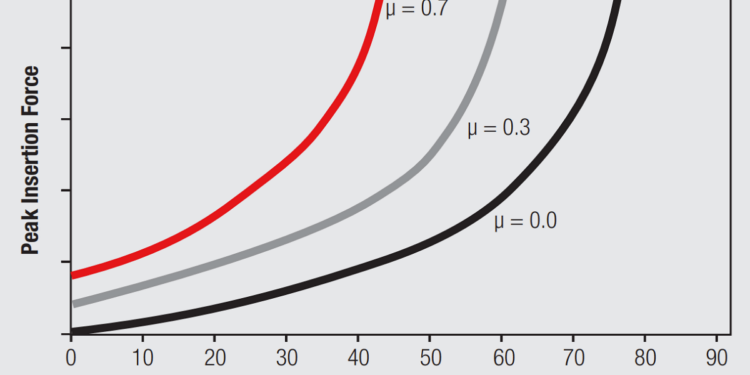
The variation of mating wear/durability as a function of contact force is a good example of normal force optimization. The kinetics of the wear process were discussed in Chapter I/1.3.2 The Mechanical Interface: Friction and Wear/Durability. The following equation provides a parametric format for discussion of some of the major factors influencing the wear process.

where, V is the wear volume, Fn is the contact normal force, L is the mating length or fretting distance, H is the hardness, and k, the wear coefficient, is a parameter including effects of roughness, lubricity, contact geometry and normal force.

RelatedPosts

Polymer Materials and Processing

What is RF Connector

Connector Materials and Processes

The wear volume, V, represents the volume of material removed, the wear particle in Figure 1.17 (Page 30). It can be related to the loss in thickness of the contact finish from the fact that V is the product of the contact area and the thickness removed.

Note that given this formulation, the thickness removed increases as the contact area decreases.

The dependence on L, the mating length or fretting length, is straight forward. Similarly for hardness, H, in that hard materials wear less than soft materials for a given contact configuration and contact force.

Note that the contact force, Fn, appears in two places in the equation. V increases linearly with contact force for a given value of k and Fn also appears, parametrically, in k itself. k is complex in its variation, with multiple parameters. For example the wear rate for a lubricated surface will be lower than that for a non lubricated surface, but as contact force increases the effects of lubricity may be overcome by a transition from a burnishing to an adhesive wear regime. Thus wear rates can vary significantly depending on the interactions among the multiple parameters included in k. The key point about contact force and wear is that wear rates increase linearly with Fn and can increase discontinuously and dramatically if the wear kinetics transition from burnishing to adhesive wear. This is an important consideration at high contact force.

Related

Source: Wurth elektronik

Recent Posts

Non-Magnetic Interconnects

23.4.2025
24

10 Tips for Ensuring Reliability of Discrete Wire Assemblies

20.2.2025
55

Polymer Materials and Processing

31.1.2025
47

Basic PCB Technology Overview

1.7.2025
17

What is RF Connector

17.12.2024
9

Creepage and Clearance of Connector

25.7.2025
16

Microwave Multi Line Connectors Mounting and Handling Precautions

17.12.2024
3

BASIC PCB Design Rules – Layout

1.7.2025
29

MEMR RF Relay for Space Compact Redundancy Ring

17.12.2024
3

Connector Temperature Rise and Derating

13.1.2023
22

Upcoming Events

Sep 22
September 22 @ 13:00 - September 25 @ 15:15 EDT

Pre Cap Visual Inspection per Mil-Std-883 (TM 2017)

Sep 30
September 30 @ 12:00 - October 2 @ 14:00 EDT

MIL-Std-883 TM 2010

Oct 17
12:00 - 14:00 EDT

External Visual Inspection per MIL-STD-883 TM 2009

Oct 21
October 21 @ 12:00 - October 23 @ 14:15 EDT

Space and Military Standards for Hybrids and RF Microwave Modules

Nov 4
November 4 @ 12:00 - November 6 @ 14:15 EST

Wirebond Materials, Processes, Reliability and Testing

View Calendar

Popular Posts

  • Buck Converter Design and Calculation

    0 shares
    Share 0 Tweet 0
  • Boost Converter Design and Calculation

    0 shares
    Share 0 Tweet 0
  • Flyback Converter Design and Calculation

    0 shares
    Share 0 Tweet 0
  • LLC Resonant Converter Design and Calculation

    0 shares
    Share 0 Tweet 0
  • What is a Dielectric Constant and DF of Plastic Materials?

    4 shares
    Share 4 Tweet 0
  • Ripple Current and its Effects on the Performance of Capacitors

    3 shares
    Share 3 Tweet 0
  • Dual Active Bridge (DAB) Topology Explained

    0 shares
    Share 0 Tweet 0
  • How to Design an Inductor

    0 shares
    Share 0 Tweet 0
  • MLCC Case Sizes Standards Explained

    0 shares
    Share 0 Tweet 0
  • MLCC and Ceramic Capacitors

    0 shares
    Share 0 Tweet 0

Newsletter Subscription


Passive Components Blog

© EPCI - Leading Passive Components Educational and Information Site

  • Home
  • Privacy Policy
  • EPCI Membership & Advertisement
  • About

No Result
View All Result
  • Home
  • Knowledge Blog
  • Premium Suppliers

© EPCI - Leading Passive Components Educational and Information Site

This website uses cookies. By continuing to use this website you are giving consent to cookies being used. Visit our Privacy and Cookie Policy.
Go to mobile version