











Passive Components Blog
No Result
View All Result
  • Home
  • News
    • All
    • Aerospace & Defence
    • Antenna
    • Applications
    • Automotive
    • Capacitors
    • Circuit Protection Devices
    • electro-mechanical news
    • Filters
    • Fuses
    • Inductors
    • Industrial
    • Integrated Passives
    • inter-connect news
    • Market & Supply Chain
    • Market Insights
    • Medical
    • Modelling and Simulation
    • New Materials & Supply
    • New Technologies
    • Non-linear Passives
    • Optoelectronics and Isolation
    • Oscillators
    • Passive Sensors News
    • Resistors
    • RF & Microwave
    • Telecommunication
    • Weekly Digest

    Bourns Adds ACXX57SQ Air Coil Inductors for RF Design

    Samsung Electro-Mechanics MLCC capacitor solutions for high-voltage converter snubbing and GPU power delivery

    Samsung MLCC Options for 1 MW AI Rack Power

    Frenetic planar ER transformer simulation for a 5 kW 800 V-to-50 V PSFB converter, showing low-profile core geometry and high-current planar winding arrangement

    5 kW 800 V-to-50 V PSFB Transformer Design for Data Centers

    Samtec 100-CM 1.0 mm vertical solderless compression-mount 50 ohm RF PCB connector

    Samtec 100-CM 1.0 mm RF Connectors Extend to 120 GHz

    Exxelia PM film capacitor and passive-component technologies for BepiColombo space electronics

    Exxelia Passive Components Support BepiColombo Mission

    TT Electronics OPI1268T green through-hole phototransistor optocoupler used for optical isolation in power systems.

    Optocoupler Reliability: Designing Optical Isolation for 25-Year Grid Assets

    TDK B43657 and B43658 ultra-compact snap-in aluminum electrolytic capacitors for 500 V DC power-supply and DC-link applications

    TDK Extends Compact Snap-In Capacitors to 500 V for AI Servers

    Stackpole RNAN aluminium nitride thin-film chip resistors in 0603, 0805, 1206 and 2512 package sizes for precision high-power electronics

    Stackpole RNAN AlN Thin-Film Resistors Reach 6 W

    binder angled M12-A midmount panel-mount PCB connector for centric board mounting, showing compact front-facing industrial connector geometry

    binder Adds Midmount M12-A PCB Connectors for Slim Sensors

    Trending Tags

    • Ripple Current
    • RF
    • Leakage Current
    • Tantalum vs Ceramic
    • Snubber
    • Low ESR
    • Feedthrough
    • Derating
    • Dielectric Constant
    • New Products
    • Market Reports
  • Knowledge Blog
  • Dossiers
    • AI Hardware Dossier
    • Automotive Dossier
    • Industrial Robotics Dossier
    • Power Converter Dossier
    • Capacitor Dossier
    • Resistor Dossier
    • Inductor Dossier
    • Circuit Protection Dossier
  • Suppliers
    • Who is Who
  • PCNS
    • PCNS 2025
    • PCNS 2023
    • PCNS 2021
    • PCNS 2019
    • PCNS 2017
  • Events
  • Home
  • News
    • All
    • Aerospace & Defence
    • Antenna
    • Applications
    • Automotive
    • Capacitors
    • Circuit Protection Devices
    • electro-mechanical news
    • Filters
    • Fuses
    • Inductors
    • Industrial
    • Integrated Passives
    • inter-connect news
    • Market & Supply Chain
    • Market Insights
    • Medical
    • Modelling and Simulation
    • New Materials & Supply
    • New Technologies
    • Non-linear Passives
    • Optoelectronics and Isolation
    • Oscillators
    • Passive Sensors News
    • Resistors
    • RF & Microwave
    • Telecommunication
    • Weekly Digest

    Bourns Adds ACXX57SQ Air Coil Inductors for RF Design

    Samsung Electro-Mechanics MLCC capacitor solutions for high-voltage converter snubbing and GPU power delivery

    Samsung MLCC Options for 1 MW AI Rack Power

    Frenetic planar ER transformer simulation for a 5 kW 800 V-to-50 V PSFB converter, showing low-profile core geometry and high-current planar winding arrangement

    5 kW 800 V-to-50 V PSFB Transformer Design for Data Centers

    Samtec 100-CM 1.0 mm vertical solderless compression-mount 50 ohm RF PCB connector

    Samtec 100-CM 1.0 mm RF Connectors Extend to 120 GHz

    Exxelia PM film capacitor and passive-component technologies for BepiColombo space electronics

    Exxelia Passive Components Support BepiColombo Mission

    TT Electronics OPI1268T green through-hole phototransistor optocoupler used for optical isolation in power systems.

    Optocoupler Reliability: Designing Optical Isolation for 25-Year Grid Assets

    TDK B43657 and B43658 ultra-compact snap-in aluminum electrolytic capacitors for 500 V DC power-supply and DC-link applications

    TDK Extends Compact Snap-In Capacitors to 500 V for AI Servers

    Stackpole RNAN aluminium nitride thin-film chip resistors in 0603, 0805, 1206 and 2512 package sizes for precision high-power electronics

    Stackpole RNAN AlN Thin-Film Resistors Reach 6 W

    binder angled M12-A midmount panel-mount PCB connector for centric board mounting, showing compact front-facing industrial connector geometry

    binder Adds Midmount M12-A PCB Connectors for Slim Sensors

    Trending Tags

    • Ripple Current
    • RF
    • Leakage Current
    • Tantalum vs Ceramic
    • Snubber
    • Low ESR
    • Feedthrough
    • Derating
    • Dielectric Constant
    • New Products
    • Market Reports
  • Knowledge Blog
  • Dossiers
    • AI Hardware Dossier
    • Automotive Dossier
    • Industrial Robotics Dossier
    • Power Converter Dossier
    • Capacitor Dossier
    • Resistor Dossier
    • Inductor Dossier
    • Circuit Protection Dossier
  • Suppliers
    • Who is Who
  • PCNS
    • PCNS 2025
    • PCNS 2023
    • PCNS 2021
    • PCNS 2019
    • PCNS 2017
  • Events
No Result
View All Result
Passive Components Blog
No Result
View All Result

Don’t let ESR waste power and cook capacitors

30.5.2018
Reading Time: 3 mins read
A A

Source: EDN article

Bill Schweber explains some basic understanding of capacitor’s ESR and why it is of interest.

RelatedPosts

Bourns Adds ACXX57SQ Air Coil Inductors for RF Design

Samsung MLCC Options for 1 MW AI Rack Power

5 kW 800 V-to-50 V PSFB Transformer Design for Data Centers

Back in school when being introduced to the basics of electrical engineering, we learned that the ideal capacitor was a simple, basic reactive element. It was easily modeled with capacitive reactance

XC = 1/(2πfC)

where f is the frequency and C is the capacitance value. Then, in some (but not all) courses, that idealistic façade was stripped away and we learned that reality is not so simple. There’s an important real-world aspect to the ideal capacitor, called its equivalent series resistance (ESR), which quantifies the capacitor’s effective resistance RS to RF currents.

This ESR actually has multiple constituent elements, including the part contributed by the electrodes and terminal leads, as well as that due to the dielectric, plate material, electrolytic solution, all as measured at a particular frequency. If you look at ESR in terms of the actual series resistance, the leakage resistance, and the dielectric loss, ESR goes from being just a resistor in series with an ideal capacitor to something more complicated, Figure 1. (Note that real capacitors also have a complementary parasitic self-inductance called equivalent series inductance or ESL, but that’s another story for another time.)


Figure 1 The theoretical capacitor is a simple reactive element, but a real one has equivalent series resistance due to ohmic series resistance, leakage resistance, and dielectric loss. (Image courtesy of QuadTech, Incorporated)

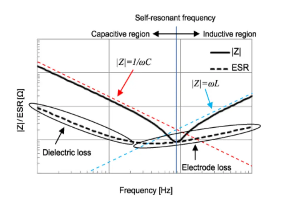
Why should we worry about ESR? For basic DC-only blocking circuits, ESR may have little impact. However, when you are designing a switching power supply or an RF circuit, ESR obviously affects your modeling, and real-world performance of the circuit. ESR shifts and degrades the resonance of the circuit in which the capacitor is functioning, as well as the Q (quality factor) of the circuit. ESR is a function of frequency, obviously, as well as capacitor type, materials, construction, capacitor value, and many other factors, Figure 2.

Figure 2 ESR is a function of many factors including operating frequency and capacitor material and type (Image courtesy of Murata)

The implications of ESR go beyond performance. As a “resistor” it also creates thermal power dissipation P as a function of the current through the capacitor, with P = I2RS. Not only don’t we like to waste power in most cases in terms of energy use (cost) and run time, but this dissipation adds to the thermal load of the system. Even if it doesn’t burden the system, it can soon exceed the thermal rating of the capacitor itself. If you go through the numbers using, for example, a basic 0.47 μF capacitor with modest ESR of about 0.1 Ω at 1 GHz will dissipate will around 75 mW – which is not much or is a lot, depending on the circuit and system details, and capacitor rating.

The obvious question is how do you determine ESR? For most engineers, the answer is clear: you look at the vendor data sheet numbers and the graph of ESR versus frequency. Reputable vendors provide detailed ESR specifications which define not only the value but also how they determine it.

If you want to measure ESR yourself, it’s not an easy task. An article in Microwave Journal, “The Methods and Problems of Capacitor ESR Measurement,” (free, but registration required) went into considerable detail on a long-standing and accepted way of doing so along with its limitations, as well as a more-advanced technique; the various vendors may use other approaches. Regardless of which one you try, there are many test and instrumentation subtleties, as there always are when dealing with signals and components at GHz and higher frequencies.

Has one of your design ever been compromised by excessive ESR that you did not expect? Have you ever tried to dig into the details of the ESR of a specific capacitor you were using, or tried to measure ESR yourself?

Bill Schweber is an EE who has written three textbooks, hundreds of technical articles, opinion columns, and product features.

References

  1. Murata, “What are impedance/ESR frequency characteristics in capacitors?“
  2. QuadTech, “Equivalent Series Resistance (ESR) of Capacitors“

featured image credit: Murata

Related

Recent Posts

Samsung Electro-Mechanics MLCC capacitor solutions for high-voltage converter snubbing and GPU power delivery

Samsung MLCC Options for 1 MW AI Rack Power

18.9.2026
5
Frenetic planar ER transformer simulation for a 5 kW 800 V-to-50 V PSFB converter, showing low-profile core geometry and high-current planar winding arrangement

5 kW 800 V-to-50 V PSFB Transformer Design for Data Centers

18.9.2026
4
Exxelia PM film capacitor and passive-component technologies for BepiColombo space electronics

Exxelia Passive Components Support BepiColombo Mission

16.9.2026
23
TDK B43657 and B43658 ultra-compact snap-in aluminum electrolytic capacitors for 500 V DC power-supply and DC-link applications

TDK Extends Compact Snap-In Capacitors to 500 V for AI Servers

16.9.2026
31

Samsung MLCC Revenue Seen Above KRW 8T by 2027, Murata EOL Actions Reshape Supply

11.9.2026
74

LG Innotek Demonstrates FC-BGA Substrates With Embedded Silicon Capacitors for AI Power Delivery

10.9.2026
55

Emerging Capacitor Markets in Fusion Energy

10.9.2026
58
onsemi solid-state transformer concept for 800 V HVDC AI data center power conversion with SiC modules, DC-link capacitors and high-frequency magnetics

Solid-State Transformers for 800 V AI Data Centers: Passive Component Design Considerations

9.9.2026
123
TDK CN series 10 µF 100 V X7R soft-termination multilayer ceramic capacitor in 3225 EIA 1210 package

TDK Releases 100 V Soft-Termination X7R MLCCs 10 uF in 3225 Package

9.9.2026
38

Upcoming Events

Sep 29
16:00 - 17:00 CEST

Cybersecurity 2026

Sep 30
15:00 - 16:00 CEST

Positronic Space and Military Connectors

Oct 14
17:00 - 18:00 CEST

Live Demo! Discover KYOCERA AVX Antenna Integrator Studio (AIS)

View Calendar

Popular Posts

  • Buck Converter Design and Calculation

    0 shares
    Share 0 Tweet 0
  • LLC Resonant Converter Design and Calculation

    0 shares
    Share 0 Tweet 0
  • Boost Converter Design and Calculation

    0 shares
    Share 0 Tweet 0
  • Flyback Converter Design and Calculation

    0 shares
    Share 0 Tweet 0
  • Capacitor Charging and Discharging

    0 shares
    Share 0 Tweet 0
  • Resistor Symbols

    0 shares
    Share 0 Tweet 0
  • MLCC and Ceramic Capacitors

    0 shares
    Share 0 Tweet 0
  • Earthing Systems and IEC Classification Explained

    0 shares
    Share 0 Tweet 0
  • Audio Capacitors: Choosing Capacitors for Crossover Circuits

    0 shares
    Share 0 Tweet 0
  • Capacitor Symbols

    0 shares
    Share 0 Tweet 0

Newsletter Subscription


Passive Components Blog

© 2015–2026
All rights reserved

  • Home
  • Privacy Policy
  • EPCI Membership & Advertisement
  • About

No Result
View All Result
  • Home
  • Knowledge Blog
  • Dossiers
  • PCNS

© 2015–2026
All rights reserved











