Passive Components Blog
No Result
View All Result
  • Home
  • NewsFilter
    • All
    • Aerospace & Defence
    • Antenna
    • Applications
    • Automotive
    • Capacitors
    • Circuit Protection Devices
    • electro-mechanical news
    • Filters
    • Fuses
    • Inductors
    • Industrial
    • Integrated Passives
    • inter-connect news
    • Market & Supply Chain
    • Market Insights
    • Medical
    • Modelling and Simulation
    • New Materials & Supply
    • New Technologies
    • Non-linear Passives
    • Oscillators
    • Passive Sensors News
    • Resistors
    • RF & Microwave
    • Telecommunication
    • Weekly Digest

    Murata Releases Worlds First 10µF/50V Automotive MLCC in 0805 Size

    Würth Elektronik Extends High Saturation Flat-Wire Power Inductors Line

    Vishay Expands Automotive High Frequency Thin Film Chip Resistors

    Advancements and Applications of Switch Capacitor Power Converters

    KYOCERA AVX Releases Robust Vertical-Mating Battery Connectors

    Accelerating Full Bridge LLC Resonant Converter Design with Frenetic AI

    Samsung Delivers Silicon Capacitors to Marwell AI Systems

    Stackpole Releases Low VCR High Voltage Chip Resistors

    June 2025 Interconnect, Passives and Electromechanical Components Market Insights

    Trending Tags

    • Ripple Current
    • RF
    • Leakage Current
    • Tantalum vs Ceramic
    • Snubber
    • Low ESR
    • Feedthrough
    • Derating
    • Dielectric Constant
    • New Products
    • Market Reports
  • VideoFilter
    • All
    • Antenna videos
    • Capacitor videos
    • Circuit Protection Video
    • Filter videos
    • Fuse videos
    • Inductor videos
    • Inter-Connect Video
    • Non-linear passives videos
    • Oscillator videos
    • Passive sensors videos
    • Resistor videos

    Accelerating Full Bridge LLC Resonant Converter Design with Frenetic AI

    Understanding Switched Capacitor Converters

    Coupled Inductors Circuit Model and Examples of its Applications

    Inductor Resonances and its Impact to EMI

    Highly Reliable Flex Rigid PCBs, Würth Elektronik Webinar

    Causes of Oscillations in Flyback Converters

    How to design a 60W Flyback Transformer

    Modeling and Simulation of Leakage Inductance

    Power Inductor Considerations for AI High Power Computing – Vishay Video

    Trending Tags

    • Capacitors explained
    • Inductors explained
    • Resistors explained
    • Filters explained
    • Application Video Guidelines
    • EMC
    • New Products
    • Ripple Current
    • Simulation
    • Tantalum vs Ceramic
  • Knowledge Blog
  • Suppliers
    • Who is Who
  • Events
No Result
View All Result
Passive Components Blog
No Result
View All Result

Electrical equipment evolution in civil aeronautics: Handling high power up to 1,000kW from the designer point of view

21.6.2019
Reading Time: 5 mins read
A A

Source: Electronics 360 article

by Bruno Cogitore, Marie Evrard and Rebecca Charles for Exxelia

RelatedPosts

Murata Releases Worlds First 10µF/50V Automotive MLCC in 0805 Size

Würth Elektronik Extends High Saturation Flat-Wire Power Inductors Line

Vishay Expands Automotive High Frequency Thin Film Chip Resistors

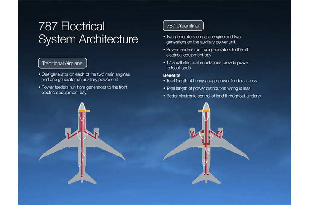
For many years, Airbus and Boeing aircraft manufacturers have been moving toward a more electric aircraft, gradually replacing equipment traditionally powered by mechanical or hydraulic power with electric power. This move paves the way for increased reliability, better efficiency and availability, reduced mass and optimized maintenance. As a well-known designer and manufacturer of magnetic components for the aerospace industry, Exxelia is impacted by this evolution, well beyond the growing market it represents.

Electrical force

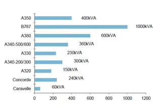
What is the electric power level in a modern, medium-haul, civil aircraft? The Boeing 787 can deliver peak power for a few minutes at nearly 1,000 kW, while the Airbus A320neo can deliver nearly 600 kW. Only about 15% of the equipment in this generation of aircraft is electrical, which suggests that although the power involved is already significant, the scope for progress is still enormous.

Is it possible to increase power without exceeding the limit of electrical equipment in an aircraft? Experts say no. Many constraints in terms of weight, volume and costs make this impossible. Yet, various methods can be used to overcome this difficulty, like improving equipment efficiency or equipment sharing through the management of a network Figure 2: Roughly 15% of today’s aircraft equipment is electrical Source: Safranfor generating, transporting and distributing electrical energy. Of course, the number and power of electrical equipment will increase slightly, but become more and more specific and complex because of the multiple functions they will have to satisfy, and all of the equipment will have to work together without disruption.

Figure 1: The Boeing 787 can deliver peak power for a few minutes at nearly 1,000 kW, while the Airbus A320neo can deliver nearly 600 kW. Source: Safran

Electrical equipment design

The primary consequence of this mutation impacts the design of electrical equipment, which is often composed of energy conversion chains. The combination of several cascaded converters must be designed via a multi-physical approach, taking into account power electronics, thermals and mechanics at the very least.

In recent years, several technological revolutions have considerably improved performance of converters and at higher switching frequencies. Wideband gap transistors (gallium nitride, silicon carbide) have considerably reduced switching losses. Progress made in microelectronics has allowed development of control, drive and regulation circuits (field-programmable gate arrays, microcontroller units), which also work much more quickly. To improve performance, researchers and engineers also worked on the converter structure and developed more efficient architectures and topologies. This led to the generalization of previously atypical operating principles, such as all forms of soft or resonant switching, as well as dual/multiple active bridges.

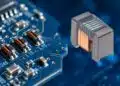
However, these technological innovations have made the operating principles of converters more complex to study and understand. This is particularly true for one fundamental element of converters: magnetic components (MC).

The way MCs are used is innovative and no longer resembles what was taught about electromagnetism in engineering school. To understand how an MC works, it is necessary to analyze and understand how the converter where the MC is inserted works, and then identify the worst case of operation. This depends on a large number of parameters, including the converter input voltage, frequency and temperature, so that the MC delivers the expected performances in all possible configurations of use. In other words, designing the MC needs certain skills in power electronics.

The increase in power level combined with the requirement to miniaturize electrical equipment increases the thermal challenge imposed on the MC, which will heat more in a smaller space. During the design step, it is therefore essential to evaluate the thermal behavior of the MC as accurately as possible to define and approach its thermal limits and achieve an optimal balance between size (a MC that is too large or heavy) and reliability (a MC that heats up too much will not be reliable). Designing MCs now also requires a minimum level of thermal competence.

Finally, there is the challenge of industrialization, which is the reproducibility in manufacturing, both on the key functions of the MC and on their tolerances. It is a matter of controlling, not cancelling, the defects and drawbacks of the MC.

The innovative operation of converters takes advantage of the defects of the MCs. These defects must remain relatively stable from one copy to another. The technologies and manufacturing processes chosen to produce the MCs must make it possible to obtain values of leakage inductance and parasitic capacitances that are not variable. At the design step, this requires mathematical models available to accurately assess the values of these defects. There are even some converters that use the saturation property of magnetic components to limit the energy to be stored or released under certain conditions. It is then necessary to design the component, an inductance in general, at the middle of the saturation curve of its magnetic circuit, which is contrary to historical habits in this field.

The example below shows that the complex and innovative aspects of converters have a direct impact on the design of MCs.

The converter shown in the figure below has only been used in aeronautics for about 15 years. It is a 12-phase rectifier with three stages: an autotransformer, followed by two groups of six diodes, then two interphase chokes. The rectifier creates a 270 V (or 540 V) DC network from the 115 V (or 230 V), 400 Hz, three-phase network generated by the aircraft’s engines. This topology was studied a few decades ago by a team of international researchers and industrialists who wanted to use this more efficient topology first had to understand the team’s scientific publications. It turned out that the unavoidable defects of the two magnetic components significantly degrade the functioning of the rectifier. Exxelia’s design team had to understand all these aspects before developing a design method for these two atypical MCs. One objective was to reduce the impact of the defects of the two MCs on the rectifier operation.

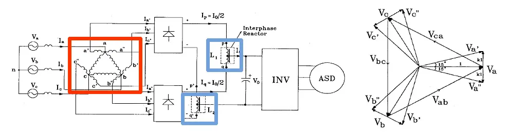
Fig.2. The rectifier creates a 270 V (or 540 V) DC network from the 115 V (or 230 V) 400 Hz three-phase network generated by the aircraft’s engines. Source: IEEE

The professions of electrical equipment designer and magnetic component designer are both evolving at high speeds and are increasingly linked to each other. MC designers can no longer simply use the few rules of electromagnetism learned at school combined with the experience acquired at his or her company. They must now be interested in the converter in which their component will operate, and must evaluate the thermal behavior of the component. The designer must also control and define the manufacturing process that will control the defects of the components — all at an increasingly competitive price.

Summary
This leads to a profound change in the profession of MC designer. Faced with this evolution and with meeting the new challenges of this more electric aircraft race, the designer/customer link must inevitably be strengthened, especially during the development of equipment.

featured image source: Boeing


Recent Posts

Würth Elektronik Extends High Saturation Flat-Wire Power Inductors Line

26.6.2025
4

Vishay Expands Automotive High Frequency Thin Film Chip Resistors

26.6.2025
3

Advancements and Applications of Switch Capacitor Power Converters

25.6.2025
8

Accelerating Full Bridge LLC Resonant Converter Design with Frenetic AI

24.6.2025
10

Murata Announces 0402 Automotive Chip Ferrite Beads for V2X

19.6.2025
27

Role of High-Q Ceramic Filters to Overcome GNSS Jamming

19.6.2025
17

TDK Releases Automotive Power-Over-Coax Inductor for Filters

18.6.2025
20

Advanced Conversion Announces Mass Production of 200C Film Capacitors

18.6.2025
28

Bourns Introduces New Automotive Grade BMS Signal Transformer

17.6.2025
14

YAGEO Releases High Isolation Transformer for 1500VDC Applications

12.6.2025
26

Upcoming Events

Jul 23
13:00 - 14:00 CEST

PCB design for a Smartwatch

View Calendar

Popular Posts

  • Buck Converter Design and Calculation

    0 shares
    Share 0 Tweet 0
  • Boost Converter Design and Calculation

    0 shares
    Share 0 Tweet 0
  • Flyback Converter Design and Calculation

    0 shares
    Share 0 Tweet 0
  • What is a Dielectric Constant and DF of Plastic Materials?

    4 shares
    Share 4 Tweet 0
  • LLC Resonant Converter Design and Calculation

    0 shares
    Share 0 Tweet 0
  • Ripple Current and its Effects on the Performance of Capacitors

    3 shares
    Share 3 Tweet 0
  • How to Design an Inductor

    0 shares
    Share 0 Tweet 0
  • Dual Active Bridge (DAB) Topology Explained

    0 shares
    Share 0 Tweet 0
  • SEPIC Converter Design and Calculation

    0 shares
    Share 0 Tweet 0
  • Why Low ESR Matters in Capacitor Design

    0 shares
    Share 0 Tweet 0

Newsletter Subscription


Passive Components Blog

© EPCI - Leading Passive Components Educational and Information Site

  • Home
  • Privacy Policy
  • EPCI Membership & Advertisement
  • About

No Result
View All Result
  • Home
  • Knowledge Blog
  • Premium Suppliers

© EPCI - Leading Passive Components Educational and Information Site

This website uses cookies. By continuing to use this website you are giving consent to cookies being used. Visit our Privacy and Cookie Policy.
Go to mobile version