


This article, based on the Würth Elektronik and onsemi webinar “Simplifying Vehicle Development with Automotive Ethernet and Zonal Smart Switch Technologies,” examines the system‑level motivations behind zonal architectures and 48 V power nets, and details how smart switches and passive components enable safe, EMC‑robust implementations.
The Würth Elektronik webinar further explores electromagnetic compatibility (EMC) fundamentals, device‑level building blocks, and a modular front‑lighting reference design as a concrete example.
Introduction
Automotive electrical/electronic (E/E) architectures are transitioning from legacy, ECU‑centric designs to software‑defined, zonal platforms interconnected by automotive Ethernet. This shift is driven by the need to reduce wiring harness mass, manage software complexity across hundreds of ECUs, and support automated driving with stringent safety and EMC requirements.
The primary engineering challenge addressed is how to architect and realize scalable zonal power and communication networks that reduce wiring, support software‑defined behavior, and remain reliable under automotive EMC, safety, and thermal constraints.
Key points
- Legacy architectures have evolved from a few ECUs to over 100 ECUs per vehicle, driving wiring harness weight up to approximately 70 kg and increasing design, manufacturing, and integration cost.
- Zonal E/E architectures with central compute, zonal controllers, and automotive Ethernet (e.g., 10BASE‑T1S, 100BASE‑T1, 1000BASE‑T1) reduce harness length and centralize power and function control.
- Moving the main distribution from 12 V to 48 V allows thinner conductors and lighter harnesses but requires components and protection able to handle higher steady‑state and transient voltages.
- Smart high‑side switches and eFuses with current monitoring, idle‑mode control, harness protection, and capacitive load handling replace classical fuse boxes and enable diagnostics, remote power cycling, and intelligent load shedding.
- Centralized power distribution units and zonal controllers reserve energy for steer‑by‑wire and brake‑by‑wire under fault conditions by shedding non‑critical loads such as heating and seat comfort.
- EMC must be treated from the earliest PCB design stage, considering differential‑mode and common‑mode noise, coupling mechanisms (galvanic, inductive, capacitive, radiative), and early pre‑compliance testing.
- Würth Elektronik provides automotive‑qualified passives such as common‑mode chokes (e.g., CNSA), molded and flat‑wire power inductors (e.g., XHMA, HCFAT), solder contact fingers (CSFA), and cable ferrites optimized for specific frequency ranges.
- A modular front‑lighting reference design with onsemi Ethernet (NCV7410) and LED driver ICs (NCV78964, NCV78925) demonstrates practical integration of 10BASE‑T1S connectivity, multi‑channel LED drivers, and optimized passives for efficiency and EMI compliance.
- Future (circa 2028+) vehicles are expected to use door‑zone controllers, automotive Ethernet for most in‑vehicle networking, 48 V modular wiring looms, and software‑defined lighting and functions, with increasing emphasis on EMI control at higher bit rates.
Evolution of vehicle architectures and wiring
Early 1990s vehicles commonly contained only a few ECUs, such as electronic ignition and a radio, with many functions implemented using direct wiring from mechanical switches to loads. Headlamp power, for example, flowed directly through a dashboard switch, requiring a thick wire running from the switch to the bulb and back. Wiring looms were relatively simple and light.
As safety and comfort features such as ABS, airbags, electric windows, central locking, and driver assistance were added incrementally, OEMs often introduced new ECUs per function, leading to vehicles with over 100 ECUs. Domain‑type architectures with dedicated lighting ECUs and similar controllers reduced some wiring duplication but did not fundamentally address overall loom complexity and the proliferation of software variants. Harness mass in high‑end vehicles can now reach roughly 70 kg, with significant design and tooling capital expenditure as well as high assembly effort.
Software complexity has grown in parallel. Each ECU typically runs its own software, and only certain combinations of versions across the network are validated as safe and functional. Updating one ECU can require coordinated updates of others to maintain a known‑good configuration, creating a significant configuration management burden.
Table 1 – Evolution from legacy to zonal architectures
| Aspect | Legacy point‑to‑point (1990s) | Domain architecture (today) | Zonal architecture (emerging) |
|---|---|---|---|
| Number of ECUs | Few | Dozens to 100+ | Reduced, domain/zonal controllers plus central compute |
| Wiring style | Direct switch‑to‑load wiring | Domain controllers plus local wiring | Short local runs within zones plus backbone trunks |
| Harness mass | Low | High, up to ~70 kg in high‑end vehicles | Reduced via consolidation and 48 V distribution |
| Diagnostics on power distribution | Minimal (fuses only) | Limited | Extensive via smart switches and zonal controllers |
| Software complexity | Low | High, many ECU images | Centralized, software‑defined with fewer application nodes |
| Suitability for automated driving | Very limited | Constrained | Designed to support high data rates and safety mechanisms |
Zonal architectures, central compute, and 48 V nets
New entrants such as Tesla and Xiaomi, unconstrained by legacy platforms, have implemented architectures centered on a powerful central compute unit connected to zonal controllers via high‑speed automotive Ethernet links. Each zone (front, rear, roof, doors, etc.) aggregates local loads and sensors, both distributing power and interfacing to local actuators such as ultrasonic sensors, trunk actuators, and lighting modules. This structural change reduces the number of long, point‑to‑point runs and allows a smaller number of power and communication trunks to serve multiple local loads.
In parallel, OEMs are introducing 48 V power nets to reduce harness cross‑section and weight, especially for high‑power loads like starter‑generators and climate control. For a given power level, raising the voltage from 12 V to 48 V allows the current to be quartered, enabling thinner wiring while providing the same delivered power. However, higher system voltages and transient envelopes increase insulation and voltage‑rating requirements on power semiconductors, inductors, chokes, and protection devices.
Table 2 – 12 V vs. 48 V power distribution (conceptual)
| Parameter | 12 V net | 48 V net | Implication |
|---|---|---|---|
| Voltage level | ~12 V nominal | ~48 V nominal | 4× higher voltage |
| Current for same power | High | ~¼ of 12 V current | Enables smaller wire cross‑section |
| Harness cross‑section | Larger | Smaller | Reduced copper usage and weight |
| Harness weight | Higher | Lower | Supports vehicle mass reduction |
| Component voltage ratings | 12 V plus transients | 48 V plus larger transients (e.g. ~70 V) | Requires higher rated semiconductors and passives |
| Primary use today | Legacy loads, low‑power ECUs | High‑power loads, emerging zonal power | Coexistence during transition phase |
Limitations of classical fuse boxes and the role of smart power
Classical fuse boxes contain a large number of discrete fuses with no built‑in diagnostics, current monitoring, or idle‑mode logic. They cannot automatically power‑cycle a failed load such as a rear camera, nor can they respond intelligently to low‑priority loads draining the battery, such as a glove compartment lamp left on for days. These limitations are incompatible with the needs of automated driving systems, which depend on reliable perception and actuation and require controlled degradation modes rather than abrupt loss of functionality.
In safety‑critical X‑by‑wire systems for steering and braking, it is essential to reserve sufficient energy for actuation even when other high‑power loads are active. Centralized power distribution units in conjunction with zonal controllers provide this coordination by monitoring load currents and switching off non‑critical loads under fault or low‑energy conditions. Smart high‑side switches and eFuses are the enabling elements for such behavior.
Table 3 – Classical fuse box vs. smart power distribution
| Feature / Capability | Classical fuse box | Smart power distribution (smart switches + eFuses) |
|---|---|---|
| Over‑current protection | Passive fuse only | Programmable limits and profiles |
| Diagnostics | None | Current monitoring, status flags, fault codes |
| Remote power cycling | Not possible | Supported via high‑side switches |
| Idle‑mode detection | Not available | Possible to disconnect abnormal long‑duration loads |
| Harness protection | Indirect, via fuse | Explicit I2t‑based cable protection |
| Integration with safety | Limited | Supports load shedding for steer‑/brake‑by‑wire |
Smart high‑side switches and eFuses
The webinar distinguishes standard high‑side switches from more advanced eFuse‑style smart switches. A standard smart high‑side switch provides controlled switching and current sensing for loads such as port‑illumination LEDs or simple actuators; it protects the semiconductor but may not offer advanced harness protection or idle‑mode features. eFuse‑type devices integrate current limiting, programmable over‑current response, and often more detailed diagnostic feedback, making them suitable for safety‑relevant loads and complex power domains.
More advanced devices combine idle‑mode operation with ‑based harness protection, explicitly modeling the thermal load on cables so that they are protected as well as the end device. Capacitive load support is provided via dedicated charging modes that allow controlled inrush to large capacitors without falsely interpreting startup behavior as a fault. onsemi is introducing families of 12 V smart FET high‑side switches, with 48 V‑capable smart switches and regulators in development or early deployment.
Table 4 – Standard smart high‑side switch vs. smart eFuse (conceptual)
| Attribute | Standard smart high‑side switch | Smart eFuse / advanced smart switch |
|---|---|---|
| Basic on/off control | Yes | Yes |
| Current monitoring | Often available | Typically available |
| Over‑current protection | Yes, device‑centric | Yes, device and harness‑centric |
| I2t harness protection | Limited or absent | Explicit, configurable |
| Idle‑mode features | Basic or absent | Enhanced (e.g., battery‑drain mitigation) |
| Capacitive load handling | May require external circuitry | Built‑in modes for capacitive loads |
| Typical use cases | Simple loads, body electronics | Safety‑critical loads, zonal power domains |
Automotive Ethernet and network connectivity
To support software‑defined behavior and automated driving, many vehicle functions are being migrated to Ethernet‑based communication. Automotive Ethernet variants such as 10BASE‑T1/T1S, 100BASE‑T1, and 1000BASE‑T1 support unshielded twisted‑pair wiring and offer scalable bandwidth for cameras, sensor fusion, body electronics, and lighting control. Zonal controllers and front‑lighting control modules may use 10BASE‑T1S for body domain communication while still maintaining CAN and LIN networks for legacy and low‑bandwidth functions.
The webinar discusses two implementation options for 10BASE‑T1S connectivity. In one approach, the node uses a standard microcontroller combined with MAC, PHY, and PMD functions, preserving much of the existing local application software. In the other, a remote control protocol (RCP) device incorporates an embedded state machine or microcontroller within the Ethernet interface, shifting more logic to central compute and enabling relatively “thin” nodes that primarily expose controlled outputs such as lighting channels.
Line protection for Ethernet nodes is implemented using common‑mode choke inductors, series capacitors, and ESD protection devices. Common‑mode chokes attenuate noise common to both lines while minimally affecting the differential signal, and capacitive coupling provides galvanic isolation and DC biasing options; ESD arrays protect against surges and electrostatic events on external connectors and cabling.
Table 5 – 10BASE‑T1S node implementation options
| Aspect | Microcontroller‑centric node | RCP‑centric “thin” node |
|---|---|---|
| Local software | Full application stack on node MCU | Minimal local logic, more in central compute |
| Hardware complexity | MAC + PHY + PMD + MCU | RCP device + simpler MCU or none |
| Reuse of existing code | High | Lower, requires re‑partitioning of functions |
| Central compute utilization | Lower | Higher (more centralized control) |
| BOM cost | Potentially higher | Potentially lower per node |
| Typical application | Complex local functions | Lighting, simple actuators, distributed I/O |
EMC fundamentals, noise mechanisms, and design flow
The EMC section emphasizes treating electromagnetic compatibility as a first‑class design constraint rather than an afterthought. EMC is divided into EMI (unwanted emissions from the application into the environment) and EMS (the application’s immunity to external noise). EMI tests generally include radiated and conducted emissions, while EMS tests include radiated and conducted immunity.
From a design‑flow perspective, EMC‑relevant decisions are cheapest during schematic capture and PCB layout. Designers are encouraged to allocate footprints for potential filter components, even if some remain unpopulated, to maintain flexibility if issues arise during testing. Once the design is stable, pre‑compliance testing on prototypes can reveal dominant emission frequencies and susceptible paths, guiding incremental layout and filtering optimizations before entering full compliance testing, which is the most expensive phase.
Noise is characterized as differential‑mode (current flowing in opposite directions on a pair of conductors) and common‑mode (current flowing in the same direction on both conductors with respect to ground). Coupling mechanisms include galvanic, inductive, capacitive, and radiative paths.
A conceptual chart can be added here showing “cost of EMC fixes” rising steeply from schematic/layout through to full compliance testing and field issues.
Passive components for power conversion and EMC
The ECU‑level block diagram presented shows dense use of DC‑DC converters, communication interfaces, and sensor links, each requiring specific passive components. Würth Elektronik’s portfolio covers both power conversion and EMI mitigation.
For communication interfaces, the CNSA series common‑mode choke is highlighted as a 1210‑size, 100 µH bifilar choke tested according to IEC 62228‑3 and intended for automotive communication interfaces. Its winding structure provides strong common‑mode attenuation while scarcely affecting the differential signal, making it suitable for Ethernet and other high‑speed links.
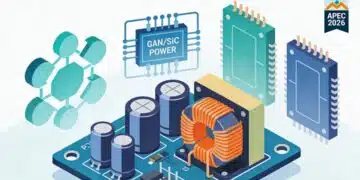
For power conversion in 48 V systems and higher‑frequency switching applications using silicon carbide (SiC) or gallium nitride (GaN), Würth Elektronik has introduced flat‑wire inductors such as the XHMA “extreme high current molded inductor for automotive” series. XHMA provides Hyperflux core material, rated currents up to about 35 A, and rated voltage up to 120 V, providing headroom for 48 V nets and their transients. The HCFAT series of flat‑wire inductors supports currents up to approximately 75 A for demanding applications such as OBC DC‑DC conversion.
Rated current measurement procedures are documented in data sheets and an application note, and designers can use the Red Expert “custom rated current calculator” by entering PCB trace length, width, and thickness to estimate allowable current for a given layout and inductor. Thermal aging is highlighted as a critical reliability factor: even if inductance remains within tolerance, the quality factor can degrade significantly under sustained high temperature, leading to increased losses and degraded EMI performance.
Grounding and cabling are addressed with solder contact fingers (CSFA) and cable ferrites. CSFA elements implement low‑impedance connections between PCB ground and chassis, are gold‑plated for corrosion resistance, and are compatible with pick‑and‑place assembly, maintaining performance under pressure and temperature cycling. Cable ferrites based on materials such as manganese‑zinc, nickel‑zinc, magnesium‑zinc, and nanocrystalline cores provide attenuation across different frequency bands and are available in various shapes to fit harness geometries.
Table 6 – Key passive component families for zonal ECUs
| Component family | Type / function | Typical application area | Key characteristics |
|---|---|---|---|
| CNSA | Common‑mode choke | Automotive communication interfaces (Ethernet, etc.) | 1210 size, ~100 µH, bifilar, IEC 62228‑3 tested |
| XHMA | Molded flat‑wire power inductor | 48 V DC‑DC, SiC/GaN converters | Hyperflux core, up to ~35 A, up to 120 V |
| HCFAT | High‑current flat‑wire inductor | OBC DC‑DC and high‑current stages | Up to ~75 A, through‑hole mounting |
| CSFA | Solder contact fingers | Ground‑to‑chassis connections | Gold‑plated, robust, pick‑and‑place capable |
| Cable ferrites | Ferrite sleeves and cores | Wiring harness EMI suppression | Multiple materials for broad frequency ranges |
A separate chart could illustrate attenuation vs. frequency for different ferrite materials, showing where each is most effective.
Modular front‑lighting reference design
The webinar concludes with a front‑lighting reference design from onsemi that uses Würth Elektronik passives to illustrate practical integration of the discussed concepts. This design is modular, consisting of multiple interconnected PCBs, each handling specific functions, such as a 10BASE‑T1S automotive Ethernet interface using NCV7410 and LED driver modules using NCV78964 and NCV78925, which provide interleaved boost stages followed by multiple buck channels for individual lighting segments.
Lighting designs may require around eleven LED channels, fed from one or more interleaved boost converters, placing heavy demands on inductor performance and EMI suppression. The reference design uses Würth Electronic inductors such as the PDA, HAPA, and LHCA series for buck and boost stages, and CBA ferrites for EMI suppression, achieving high efficiency and compliance with EMI requirements.
Table 7 – Example front‑lighting reference design building blocks
| Function block | onsemi device(s) | Würth Elektronik passives (examples) | Role in system |
|---|---|---|---|
| 10BASE‑T1S Ethernet interface | NCV7410 | CNSA chokes, ESD protection | Network connectivity to zonal/central compute |
| LED boost stage(s) | NCV78964 | Flat‑wire inductors (e.g., HAPA, LHCA) | High‑efficiency boost conversion |
| LED buck channels | NCV78925 | Shielded inductors (e.g., PDA) | Per‑channel current regulation |
| EMI suppression and filtering | – | CBA ferrites, capacitors | Conducted and radiated EMI reduction |
| Grounding and chassis coupling | – | CSFA solder fingers | Low‑impedance ground connection |
This example demonstrates the importance of selecting shielded inductors and EMI components tailored to the switching frequency and current levels of the application and integrating them with Ethernet connectivity and smart power distribution.
Forward‑looking perspective
Looking toward 2028 and beyond, the webinar anticipates vehicles adopting zonal controllers including door‑zone modules connected via automotive Ethernet and, where necessary, CAN or LIN buses, with software‑controlled lighting and other functions. Modular 48 V wiring looms are expected to become more common, with ongoing debate around extending 48 V to more loads. High‑bit‑rate links will be used across more functions than just camera systems, increasing the importance of EMI mitigation at the PHY, PCB, and cable levels.
Both onsemi and Würth Elektronik indicate that they are preparing component portfolios to support these trends, including 48 V‑capable regulators, smart high‑side switches, Ethernet PHYs and RCP devices, and inductors and filters rated for emerging voltage and frequency requirements.
Conclusion
This white paper has outlined the motivation, architecture, and enabling technologies for zonal, software‑defined automotive E/E systems built around automotive Ethernet and smart power distribution. Zonal controllers, centrally coordinated 48 V power nets, and smart high‑side switches and eFuses address the limitations of legacy fuse boxes by reducing harness mass, enabling diagnostics and remote power cycling, and ensuring safe energy allocation to steer‑by‑wire and brake‑by‑wire functions.
Achieving robust performance in such architectures requires early and systematic attention to EMC, including an understanding of differential and common‑mode noise, coupling mechanisms, and the economic value of early pre‑compliance testing. Carefully selected passive components—power inductors for 48 V converters, common‑mode chokes for Ethernet, solder contact fingers for low‑impedance grounding, and cable ferrites matched to frequency bands—are essential building blocks for EMI‑compliant designs. The modular front‑lighting reference design combining onsemi ICs with Würth Elektronik passives illustrates how these elements can be integrated into a real system meeting efficiency and EMC targets.
Engineers planning next‑generation automotive platforms can use the comparison tables in this white paper to communicate trade‑offs and design choices clearly, while using the device families and design practices highlighted here as a starting point for their own zonal controller, power distribution, and front‑lighting implementations.
References
- Würth Elektronik Group – “Simplifying Vehicle Development with Automotive Ethernet and Zonal Smart Switch Technologies” (YouTube webinar), https://youtu.be/rNsycLG6jAI
- Würth Elektronik – Product portfolio, EMC services, and Red Expert tools for automotive power and EMI design, https://www.we-online.com
- onsemi – Automotive smart FET switches, Ethernet PHYs and RCP devices, and automotive LED driver families, https://www.onsemi.com