Passive Components Blog
No Result
View All Result
  • Home
  • NewsFilter
    • All
    • Aerospace & Defence
    • Antenna
    • Applications
    • Automotive
    • Capacitors
    • Circuit Protection Devices
    • electro-mechanical news
    • Filters
    • Fuses
    • Inductors
    • Industrial
    • Integrated Passives
    • inter-connect news
    • Market & Supply Chain
    • Market Insights
    • Medical
    • Modelling and Simulation
    • New Materials & Supply
    • New Technologies
    • Non-linear Passives
    • Oscillators
    • Passive Sensors News
    • Resistors
    • RF & Microwave
    • Telecommunication
    • Weekly Digest

    Modelithics Library for MATLAB: Measurement-Based Models for Microwave and RF Passive Components

    Bourns Extends Multilayer Chip Inductors Offer for RF and Wireless Designs

    Researchers developed a polymer capacitor by combining two cheap, commercially available plastics. The new polymer capacitor makes use of the transparent material — pictured here, with vintage Penn State athletic marks visible through it — to store four times the energy and withstand significantly more heat.  Credit: Penn State

    Penn State Demonstrated Polymer Alloy Capacitor Film with 4× Energy Density up to 250C

    ECIA January 2026 Reports Strong Sales Confidence

    Vishay Unveils Ultra-Compact 0201 Thick Film Chip Resistors

    Würth Elektronik Component Data Live in Accuris

    Coilcraft Releases Automotive Common Mode Chokes

    MLCC Manufacturers Consider Price Increase as AI Demand Outpaces Supply

    YAGEO Extends Antenna Portfolio with Wi‑Fi 6E/7 and Tri‑band GNSS Solutions

    Trending Tags

    • Ripple Current
    • RF
    • Leakage Current
    • Tantalum vs Ceramic
    • Snubber
    • Low ESR
    • Feedthrough
    • Derating
    • Dielectric Constant
    • New Products
    • Market Reports
  • VideoFilter
    • All
    • Antenna videos
    • Capacitor videos
    • Circuit Protection Video
    • Filter videos
    • Fuse videos
    • Inductor videos
    • Inter-Connect Video
    • Non-linear passives videos
    • Oscillator videos
    • Passive sensors videos
    • Resistor videos

    2026 Power Magnetics Design Trends: Flyback, DAB and Planar

    Enabling Software‑Defined Vehicle Architectures: Automotive Ethernet and Zonal Smart Power

    Calculating Resistance Value of a Flyback RC Snubber 

    One‑Pulse Characterization of Nonlinear Power Inductors

    Thermistor Linearization Challenges

    Coaxial Connectors and How to Connect with PCB

    PCB Manufacturing, Test Methods, Quality and Reliability

    Transformer Behavior – Current Transfer and Hidden Feedback

    Choosing the Right Capacitor: The Importance of Accurate Measurements

    Trending Tags

    • Capacitors explained
    • Inductors explained
    • Resistors explained
    • Filters explained
    • Application Video Guidelines
    • EMC
    • New Products
    • Ripple Current
    • Simulation
    • Tantalum vs Ceramic
  • Knowledge Blog
  • DossiersNew
  • Suppliers
    • Who is Who
  • PCNS
    • PCNS 2025
    • PCNS 2023
    • PCNS 2021
    • PCNS 2019
    • PCNS 2017
  • Events
No Result
View All Result
Passive Components Blog
No Result
View All Result

Film vs Ceramic CeraLink® Capacitors in Solar Flying Booster Applications

3.1.2024
Reading Time: 6 mins read
A A

The flying capacitor topology is a multilevel topology, that is an interesting choice especially for (but not limited to) the booster stage of a solar inverter. TDK technical note compares benefits of its CeraLink® anti-ferroelectric dielectric ceramic capacitors versus film capacitors in an example of solar inverters.

One of the well-established key requirements in solar inverters is their high efficiency. But also, their costs, size and weight are subject to continuous improvements. One approach to better fulfil all these demanding requirements simultaneously is the use of multilevel topologies. The main advantages of switching between multiple voltage levels are lower voltage stress for the semiconductors and lower ripple stress for the power chokes.

RelatedPosts

TDK Releases High Temp 175C Automotive NTC thermistors

TDK Unveils 125C Compact DC Link Film Capacitors

TDK Releases Stackable µPOL 25A Power Modules

This means that lower-voltage semiconductors can be used, which are typically cheaper. Lower ripple stress for the chokes makes smaller and thereby lighter and cheaper choke designs possible. The flying capacitor topology is a multilevel topology, that is an interesting choice especially for (but not limited to) the booster stage of a solar inverter. As its name implies, it needs a capacitor as a key element.

Introduction

In a flying capacitor multi-level converter, additional (intermediate) voltage levels (beyond the two levels naturally given by the DC link) are generated using additional capacitors.
These capacitors can float to different electric potentials depending on the switching state of the semiconductor switching structure connected to them. Therefore, they are called “flying capacitors”. Once when charged to the right voltage (e.g. half the DC link voltage), they act as a kind of “voltage sources” for the duration of the next half switching cycle, thus providing additional voltage levels.

As these capacitors are exposed to high ripple currents and switching frequencies by this modus operandi while they must maintain a certain voltage, it is important to carefully select the right components for this demanding application. In the following, we will consider some design examples and component proposals for them.

Application conditions

Throughout we assume ΔUFC = 80 Vpp as upper limit for the ripple voltage on the flying capacitor, a switching frequency of fSW = 16 kHz and a maximum peak current of Ipeak = 60A.
Therefore, the required capacitance of the flying capacitor is CFC = 24µF which can be calculated via equation. (Reference: Vincotech Technical paper “The Advantage and Operation of Flying-Capacitor Boosters”)

The ambient temperature shall be 60 °C, where it is assumed that the heating from the power modules will influence the flying capacitor not significantly. The generated heat is dissipated mainly via the PCB, where an additional smaller fraction is dissipated also through natural convection into the non-moving air. Different capacitor technologies can be considered for this application, where in the following we will have a deeper lock into TDKs film capacitor and CeraLink® ceramic capacitor technology.

Film Capacitors for PCB Mounting

TDK offers a diverse variety of film capacitors voltage and capacitance range for main costumer needs in DC-link operation. Mechanical construction varies from 2 to 4 pins and different lead space options enhance also some electrical properties as low self-inductance and high resonance frequency. With series focused on energy density, ripple current, ambient temperatures up to 125°C, and humidity protection. In addition to long life expectancy (> 100k hours) and capacitance values stability, such features are an excellent design option for the high frequency switching application. For capacitor selection, modelling data and application simulation please check our CLARA (Capacitor Life And Rating Application) website.

CeraLink® Capacitors

CeraLink® is a family of very compact ceramic capacitors for stabilizing voltages in the DC link or for use in snubber applications. These products are based on a newly patented antiferroelectric ceramic technology whose material exhibits increasing capacitance with increasing voltage. CeraLink® is designed to provide engineers with compact components, optimized for fast switching converters (e.g. SiC/GaN), converters with very tight space requirements and converters that need to withstand high operating temperatures of up to 150 °C.

It is important to note that the capacitance behaviour of CeraLink® is non-linear and optimized for operation under DC-Bias and elevated ambient temperature, see our Technical Guide or our Simulation Toolbox for further details. Given a DC-Bias level of 600 VDC and a super-imposed ripple voltage of 80 Vpp a CeraLink® FA10 700V type can be considered which offers an effective capacitance of typically 4 µF in the temperature range of 25-60 °C.

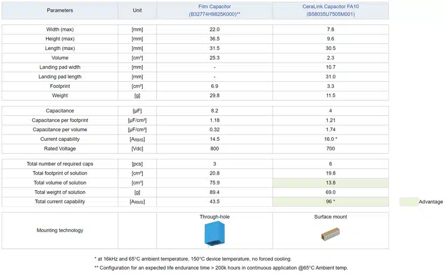
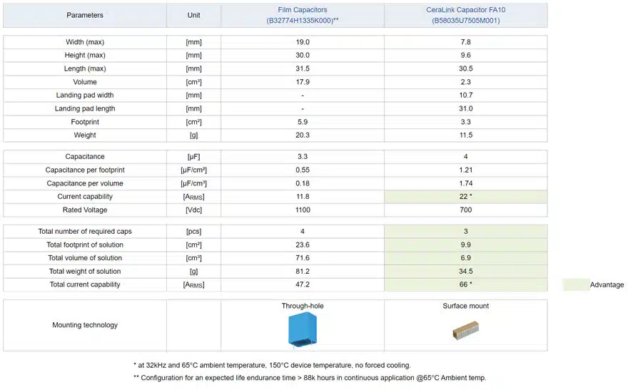
Comparison of Film Capacitors and CeraLink® Capacitors

In the following table, we compare the geometrical and electrical properties of the two considered capacitor solutions. If there are no space limitations, the film solution has more benefits in terms of costs and number of components as one or few pieces can handle the electrical requirements, whereas CeraLink® could be an option if total height of the solution is crucial or through-hole technology is not possible. Furthermore, CeraLink® also shows clear advantages if higher current capability is required and/or if switching frequency is increased.

Table 1. Film vs CeraLink ceramic capacitor solution at a switching frequency of fSW = 16 kHz, the required capacitance of the FC is CFC = 24 µF
Table 2. Film vs CeraLink ceramic capacitor solution at a switching frequency of fSW = 32 kHz, the required capacitance of the FC is CFC = 12 µF

Conclusion

The flying-capacitor booster is a high-efficient, low cost solution for solar inverter applications. The main advantages are the frequency multiplication, the lower semiconductor voltage, the lower voltage and current ripple, the lower switching losses, and the low EMI emission.

More capacitor technologies are available to meet the requirements. This note aimed to provide some selection guide tips to decide between film capacitor and ceramic CeraLink® capacitor solutions.

Related

Source: TDK

Recent Posts

Researchers developed a polymer capacitor by combining two cheap, commercially available plastics. The new polymer capacitor makes use of the transparent material — pictured here, with vintage Penn State athletic marks visible through it — to store four times the energy and withstand significantly more heat.  Credit: Penn State

Penn State Demonstrated Polymer Alloy Capacitor Film with 4× Energy Density up to 250C

19.2.2026
17

Vishay Unveils Ultra-Compact 0201 Thick Film Chip Resistors

19.2.2026
9

Würth Elektronik Component Data Live in Accuris

19.2.2026
14

Coilcraft Releases Automotive Common Mode Chokes

19.2.2026
10

MLCC Manufacturers Consider Price Increase as AI Demand Outpaces Supply

18.2.2026
157

YAGEO Extends Antenna Portfolio with Wi‑Fi 6E/7 and Tri‑band GNSS Solutions

17.2.2026
12

SCHURTER Introduces 2410 SMD Fuse for Robust AC/DC Protection

17.2.2026
11

TDK Releases High Temp 175C Automotive NTC thermistors

17.2.2026
10

TU Wien Sets New Benchmark in Superconducting Vacuum Gap nanoCapacitors

16.2.2026
11

Upcoming Events

Feb 24
16:00 - 17:00 CET

Mastering Galvanic Isolation: Ensuring Safety in Power Electronics

Mar 3
16:00 - 17:00 CET

Cybersecurity at the Eleventh Hour – from RED to CRA – Information and Discussion

Mar 21
All day

PSMA Capacitor Workshop 2026

View Calendar

Popular Posts

  • Buck Converter Design and Calculation

    0 shares
    Share 0 Tweet 0
  • Boost Converter Design and Calculation

    0 shares
    Share 0 Tweet 0
  • LLC Resonant Converter Design and Calculation

    0 shares
    Share 0 Tweet 0
  • Flyback Converter Design and Calculation

    0 shares
    Share 0 Tweet 0
  • Ripple Current and its Effects on the Performance of Capacitors

    3 shares
    Share 3 Tweet 0
  • Dual Active Bridge (DAB) Topology

    0 shares
    Share 0 Tweet 0
  • What is a Dielectric Constant and DF of Plastic Materials?

    4 shares
    Share 4 Tweet 0
  • MLCC and Ceramic Capacitors

    0 shares
    Share 0 Tweet 0
  • 3-Phase EMI Filter Design, Simulation, Calculation and Test

    0 shares
    Share 0 Tweet 0
  • MLCC Case Sizes Standards Explained

    0 shares
    Share 0 Tweet 0

Newsletter Subscription


Passive Components Blog

© EPCI - Leading Passive Components Educational and Information Site

  • Home
  • Privacy Policy
  • EPCI Membership & Advertisement
  • About

No Result
View All Result
  • Home
  • Knowledge Blog
  • PCNS

© EPCI - Leading Passive Components Educational and Information Site

This website uses cookies. By continuing to use this website you are giving consent to cookies being used. Visit our Privacy and Cookie Policy.
Go to mobile version