Passive Components Blog
No Result
View All Result
  • Home
  • NewsFilter
    • All
    • Aerospace & Defence
    • Antenna
    • Applications
    • Automotive
    • Capacitors
    • Circuit Protection Devices
    • electro-mechanical news
    • Filters
    • Fuses
    • Inductors
    • Industrial
    • Integrated Passives
    • inter-connect news
    • Market & Supply Chain
    • Market Insights
    • Medical
    • Modelling and Simulation
    • New Materials & Supply
    • New Technologies
    • Non-linear Passives
    • Oscillators
    • Passive Sensors News
    • Resistors
    • RF & Microwave
    • Telecommunication
    • Weekly Digest

    Littelfuse Adds 600W Automotive TVS Diodes for High-Energy Transient Protection

    Vishay Releases Harsh Environment Robust DC-Link Film Capacitor

    Bourns Releases Automotive High Creepage and Clearance Transformer

    Bourns Unveils Metal Powder Core High Current Low DCR Shielded Power Inductor

    Influence of Tantalum Capacitor Pellets Size on Stability During Oxide Film Formation

    Modelithics Release Discrete Components Optimization Article for RF/Microwave Designers

    Samsung Extends Capacitance of MLCC 0805 X7T 250V to 100nF

    Samtec Releases 800-Position High-Performance Array Connectors  

    DigiKey Announces Back to School Giveaway to Empower Tomorrow’s Innovators

    Trending Tags

    • Ripple Current
    • RF
    • Leakage Current
    • Tantalum vs Ceramic
    • Snubber
    • Low ESR
    • Feedthrough
    • Derating
    • Dielectric Constant
    • New Products
    • Market Reports
  • VideoFilter
    • All
    • Antenna videos
    • Capacitor videos
    • Circuit Protection Video
    • Filter videos
    • Fuse videos
    • Inductor videos
    • Inter-Connect Video
    • Non-linear passives videos
    • Oscillator videos
    • Passive sensors videos
    • Resistor videos

    Ripple Steering in Coupled Inductors: SEPIC Case

    SEPIC Converter with Coupled and Uncoupled Inductors

    Coupled Inductors in SEPIC versus Flyback Converters

    Non-Linear MLCC Class II Capacitor Measurements Challenges

    Percolation Phenomenon and Reliability of Molded Power Inductors in DC/DC converters

    Root Causes and Effects of DC Bias and AC in Ceramic Capacitors

    How to Calculate the Output Capacitor for a Switching Power Supply

    Switched Capacitor Converter Explained

    Understanding Inductor Dot Markings and Their Application in LTspice

    Trending Tags

    • Capacitors explained
    • Inductors explained
    • Resistors explained
    • Filters explained
    • Application Video Guidelines
    • EMC
    • New Products
    • Ripple Current
    • Simulation
    • Tantalum vs Ceramic
  • Knowledge Blog
  • Suppliers
    • Who is Who
  • Events
No Result
View All Result
Passive Components Blog
No Result
View All Result

Filter Bandwidth Explained

4.1.2023
Reading Time: 5 mins read
A A

This blog article from Knowles Precision Devices perform a deep dive on what bandwidth is and why we need to consider bandwidth when selecting a filter. 

In previous article, we provided a brief overview of five key filter specifications to understand, one of which was bandwidth. In this post, we will dive deeper into bandwidth by looking at the history of bandwidth, how bandwidth dictates data rate, and why the type of filter required will vary depending on an application’s bandwidth requirements.

RelatedPosts

Knowles Unveils High-Performance Safety-Certified MLCC Capacitors

Knowles Releases Inductors for Mission-Critical RF Applications

Learn How Supercapacitors Enhance Power System in Knowles eBook

First, let’s look at why bandwidth is important. In general, bandwidth is defined as the width of the passband of the bandpass filter and expressed as the frequency difference between the lower and upper 3 dB points. Bandwidth will dictate the data rate, or how quickly we can send information through a channel such as an optical fiber or a section of the radio spectrum.

A Historical Review of How to Calculate Bandwidth

To better understand bandwidth, let’s look back at some of the historical work that laid the foundation for how to consider this specification. In the 1920s, when Harry Nyquist was working on the telegraph at AT&T’s Department of Development and Research, the notion of the Nyquist Rate emerged from his work. In short, this is the theoretical minimum system bandwidth needed to detect Rs symbols per second is Rs/2 hertz.

A way to look at this more simply is to think about how signals behave in time when they are band limited. A signal such as a series of pulses that is band limited in the frequency domain gets distorted and smeared out in time. To stop these smeared-out pulses from overlapping and becoming indistinguishable at a detector, there needs to be enough bandwidth to contain all, or at least the majority, of the frequency components that make up that signal pulse. It turns out, the amount of bandwidth we need gives us the Nyquist Rate, which says that for things to make sense at the other end of a transmission, we can send pulses as fast as twice the channel bandwidth, but no faster.

Similarly, to understand why bandwidth follows when we need to increase data rate, let’s look at the Shannon-Hartley theorem that was developed in 1948 by Claude Shannon and Ralph Hartley, both researchers at Bell Labs. This theorem tells us that the maximum amount of error-free digital data that can be transmitted over a channel of a given bandwidth in the presence of noise, which is calculated using the following equation:
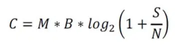
where:

  • C = Channel capacity in bits/second
  • M = Number of channels (e.g. the MIMO order)
  • B = Bandwidth in hertz
  • S = transmit power, in watts
  • N = noise on channel, in watts
  • S/N = signal to noise ratio

To increase channel capacity (data rates) we can increase bandwidth, the number of channels, or transmit power (S) or decrease the noise on the channel (N). Since this post is focused on bandwidth, we won’t get into too much detail about this, but it is worth noting that you can reduce N and increase channel capacity with filtering. For example, by including a filter with very low insertion loss, you could improve the overall noise figure, or you could address any aliasing effects that would bring out of band noise in the band of interest using a really good filter. 

How Does an Application’s Bandwidth Requirements Impact Filter Selection?

Bandwidth requirements vary widely by application as shown in Figure 1.

Figure 1. The relationship between bandwidth and frequency for a variety of common microwave systems adapted From: Demmin, Booz Allen Hamilton 68th IEEE Electronic Components and Technology Conference.

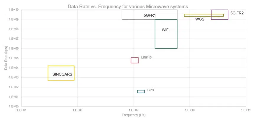
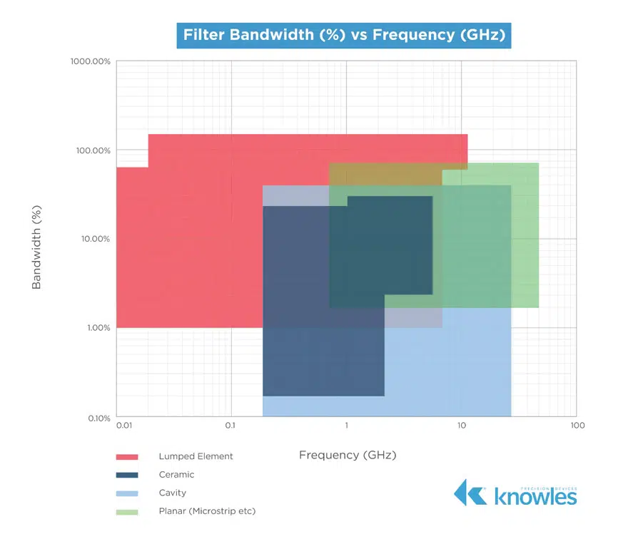
Since different applications require different data rates to successfully transmit signals without introducing noise, different types of filters are necessary as bandwidth and frequency increase. In short, the type of filter you need depends on where you are on the frequency versus bandwidth plot. More specifically, if you look back to Five Key Filter Specifications again, we also noted that we can look at the relative, or fractional, bandwidth of the filter. This is the ratio of a filter’s bandwidth to its center frequency. As shown in Figure 2, different filter technologies are capable of different fractional bandwidths.

Figure 2. Fractional bandwidths across frequencies for a variety of filter types.

Throughout this post, we looked at several different aspects of bandwidth, including how bandwidth is driven by the required channel capacity, or data rate; how different systems have different data rates, and hence, different bandwidths; and how different filter technologies are used to meet these varying bandwidth needs. In the next post in this series, we will spend more time exploring poles and zeros and how these are tools a filter designer can manipulate to improve a filter’s response.

Related

Recent Posts

Influence of Tantalum Capacitor Pellets Size on Stability During Oxide Film Formation

29.8.2025
23

Ripple Steering in Coupled Inductors: SEPIC Case

27.8.2025
14

SEPIC Converter with Coupled and Uncoupled Inductors

26.8.2025
28

Coupled Inductors in SEPIC versus Flyback Converters

26.8.2025
19

Non-Linear MLCC Class II Capacitor Measurements Challenges

19.8.2025
56

Researchers Demonstrated HfO Anti-Ferroelectric Flexible Capacitors

19.8.2025
19

Common Mistakes in Flyback Transformer Specs

15.8.2025
73

High Voltage MLCCs Meeting the Growing Demand for Efficiency in Power Conversion

12.8.2025
180

Radiation Tolerance of Tantalum and Ceramic Capacitors

8.8.2025
113

Percolation Phenomenon and Reliability of Molded Power Inductors in DC/DC converters

1.9.2025
59

Upcoming Events

Sep 3
15:30 - 17:30 CEST

How to Choose Your Magnetic Supplier

Sep 16
17:00 - 18:00 CEST

EMI Shielding Challenges

Sep 22
September 22 @ 13:00 - September 25 @ 15:15 EDT

Pre Cap Visual Inspection per Mil-Std-883 (TM 2017)

Sep 30
September 30 @ 12:00 - October 2 @ 14:00 EDT

MIL-Std-883 TM 2010

Oct 17
12:00 - 14:00 EDT

External Visual Inspection per MIL-STD-883 TM 2009

View Calendar

Popular Posts

  • Buck Converter Design and Calculation

    0 shares
    Share 0 Tweet 0
  • Boost Converter Design and Calculation

    0 shares
    Share 0 Tweet 0
  • Flyback Converter Design and Calculation

    0 shares
    Share 0 Tweet 0
  • LLC Resonant Converter Design and Calculation

    0 shares
    Share 0 Tweet 0
  • What is a Dielectric Constant and DF of Plastic Materials?

    4 shares
    Share 4 Tweet 0
  • Ripple Current and its Effects on the Performance of Capacitors

    3 shares
    Share 3 Tweet 0
  • Dual Active Bridge (DAB) Topology Explained

    0 shares
    Share 0 Tweet 0
  • How to Design an Inductor

    0 shares
    Share 0 Tweet 0
  • Core Materials, Permeability and Their Losses

    0 shares
    Share 0 Tweet 0
  • MLCC Case Sizes Standards Explained

    0 shares
    Share 0 Tweet 0

Newsletter Subscription


Passive Components Blog

© EPCI - Leading Passive Components Educational and Information Site

  • Home
  • Privacy Policy
  • EPCI Membership & Advertisement
  • About

No Result
View All Result
  • Home
  • Knowledge Blog
  • Premium Suppliers

© EPCI - Leading Passive Components Educational and Information Site

This website uses cookies. By continuing to use this website you are giving consent to cookies being used. Visit our Privacy and Cookie Policy.
Go to mobile version