Passive Components Blog
No Result
View All Result
  • Home
  • NewsFilter
    • All
    • Aerospace & Defence
    • Antenna
    • Applications
    • Automotive
    • Capacitors
    • Circuit Protection Devices
    • electro-mechanical news
    • Filters
    • Fuses
    • Inductors
    • Industrial
    • Integrated Passives
    • inter-connect news
    • Market & Supply Chain
    • Market Insights
    • Medical
    • Modelling and Simulation
    • New Materials & Supply
    • New Technologies
    • Non-linear Passives
    • Oscillators
    • Passive Sensors News
    • Resistors
    • RF & Microwave
    • Telecommunication
    • Weekly Digest

    Samtec Expands Connector Severe Environment Testing Offering

    Silicon Capacitors Market: Shaping the Foundation for Next-Gen Miniaturization Electronics

    YAGEO Releases Compact Coupled Inductors for High-Density VR Designs

    Enhancing Energy Density in Nanocomposite Dielectric Capacitors

    Advances in the Environmental Performance of Polymer Capacitors

    Vishay Releases DLA Tantalum Polymer Capacitors for Military and Aerospace

    Vishay Expanded Inductor Portfolio With More Than 2000 Stock Items 

    Paumanok Releases Capacitor Foils Market Report 2025-2030

    Modelithics Welcomes CapV as a Sponsoring MVP

    Trending Tags

    • Ripple Current
    • RF
    • Leakage Current
    • Tantalum vs Ceramic
    • Snubber
    • Low ESR
    • Feedthrough
    • Derating
    • Dielectric Constant
    • New Products
    • Market Reports
  • VideoFilter
    • All
    • Antenna videos
    • Capacitor videos
    • Circuit Protection Video
    • Filter videos
    • Fuse videos
    • Inductor videos
    • Inter-Connect Video
    • Non-linear passives videos
    • Oscillator videos
    • Passive sensors videos
    • Resistor videos

    Connector PCB Design Challenges

    Efficient Power Converters: Duty Cycle vs Conduction Losses

    Ripple Steering in Coupled Inductors: SEPIC Case

    SEPIC Converter with Coupled and Uncoupled Inductors

    Coupled Inductors in SEPIC versus Flyback Converters

    Non-Linear MLCC Class II Capacitor Measurements Challenges

    Percolation Phenomenon and Reliability of Molded Power Inductors in DC/DC converters

    Root Causes and Effects of DC Bias and AC in Ceramic Capacitors

    How to Calculate the Output Capacitor for a Switching Power Supply

    Trending Tags

    • Capacitors explained
    • Inductors explained
    • Resistors explained
    • Filters explained
    • Application Video Guidelines
    • EMC
    • New Products
    • Ripple Current
    • Simulation
    • Tantalum vs Ceramic
  • Knowledge Blog
  • Suppliers
    • Who is Who
  • Events
No Result
View All Result
Passive Components Blog
No Result
View All Result

Flat Cable Harness for Space Launcher Applications

26.2.2025
Reading Time: 7 mins read
A A

This paper presents Flat Conductor Cable Continuous technology as the most economical solution for launcher harnesses. Florent Todeschini, from ArianeGroup (Les Mureaux, France), presented this during the 5th Space Passive Component Days (SPCD), an International Symposium held from October 15th to 18th, 2024, at ESA/ESTEC in Noordwijk, the Netherlands. Published under permission from ESA SPCD organizers.

Summary

RelatedPosts

High-Density PCB Assemblies For Space Applications

Solid State Polymer Multilayer Capacitors For High Temperature Application

Graphene-Based BOSC Bank Of Supercapacitor Cells

The ESA-supported project “Improved Design of Harness for Launcher” aims to reduce the mass, volume, and cost of space launcher electrical harnesses.

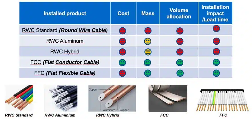
The project focuses on flat cabling as a potential solution, comparing it to traditional round cable solutions. 

The project involves the design and manufacturing of scale mockups for two harness use cases, with a focus on ease of integration, manufacturability, volume, mass, and electrical testing.

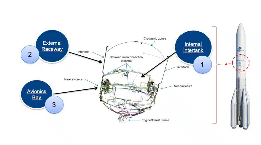
A trade-off process identified the Flat Conductor Cable Continuous technology as the most cost-effective solution for launcher harnesses, leading to the development of a flat cable conductor and connector (see Table 1.). The harness design prioritized minimizing installation footprint, organizing cables by function, and optimizing shielding and segregation to reduce noise pollution.  The redesigned harnesses for internal inter-tank and external raceway applications demonstrated significant mass savings and reduced integration time.

Table 1. Cable technology launcher harness trade-off analyses

A design process was implemented to replace traditional raceway harnesses with a single element composed of two flat parallel harnesses. This redesign aimed to minimize aerothermal impact, optimize volume allocation, and achieve mass savings. The feasibility of the design was validated through manufacturing small derisking specimens and testing the composite integration process.

Figure 1. Use cases of the FCC Flat Conductor Cable

A project developed under ESA Contract No. 4000130437/20/NL/FE successfully demonstrated the potential of Flat Flexible Cable (FFC) technologies in space and launcher applications. The project introduced several key enabling technologies, including a standardized flat cable definition, a dedicated connector, and shielding options for flat cables.  The use of FFC technology offers significant advantages, such as simplified design, automated manufacturing, reduced integration effort, and potential mass and volume savings.

The shielding of spacecraft cables will be improved by increasing contact pressure, characterizing transfer impedance, and enhancing external shielding. Additionally, a protective sheet will be developed for areas prone to thermal or mechanical friction.

CONCLUSIONS AND PERSPECTIVES 

The project developed under ESA Contract No. 4000130437/20/NL/FE has proven the potential of Flat Flexible Cable technologies to be used in different Space/Launcher applications. 

This project has brought several key enabling technologies that were not existing so forth at a European level: 

  • A standardized flat cable definition 42 mm wide, polyimide isolated, with 8 copper plain conductors with gauges extending from AWG18 to 22. 
  • A dedicated connector, rectangular, 16 contacts gauge AWG16, capable of interconnecting one or two superposed flat cables and with a backshell fixture allowing to assure the electrical continuity of the connector with the shielding (based on Axon Versatys ®). 
  • The possibility of shielding one or two superposed flat cables with a continuous copper sheet placed on both sides. 
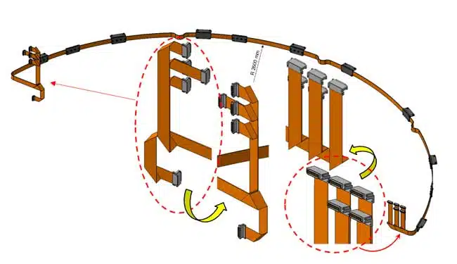
  • A proof of concept on a realistic internal inter-tank Launcher cabling, allowing to demonstrate the possibilities of the harnessing based on flat cabling (rooting including bending). 
  • A proof of concept on a realistic external Launcher raceway, including composite multi-functional integration of mechanical and thermal protection. 

The main improvements brought by the use of the flat cabling technology are depicted herein: 

  • Design: The design of flat cabling structures, considering allocation of signals is simple and straightforward. It is easy to understand where a specific electrical signal has been mapped in terms of position in the harness. The stacking also allows to include late connection needs. No specific design issue has been encountered during the design activities of both mockups. Furthermore, from our perspective, the flat cabling design process can help reduce time delivery of harness as the allocation of signals to the harnessing is more straightforward A design possibility to speed up the development time can be to pre-allocate a certain number of flat cables to the main communication paths, and then affect progressively the necessary signals to the different connectors/contacts. In case of late design needs, it is easy to add a flat cable to the stacking as is does not modify the need of new supporting brackets. This way of working might need to adapt the engineering approach at Launcher system level with an impact on the current way of specifying through internal design rules which should be adapted to this technology. There is a priori no limitation of the technology in terms of on time delivery. 
Figure 2. Intertank design FCC us example
  • Manufacturing: The manufacturing of the harness can be almost fully automated which allows to guarantee quality and cut costs. The manufacturing of the composite over-molding is based on well know processes and allows to incorporate extra functions to the harness (i.e. mechanical and thermal protection). 
  • Integration: The integration effort is mainly reduced by the fact that the harnessing footprint is minimized at launcher level, requiring a reduced set of brackets. 
  • Test and troubleshooting: As already stated on the previous point ‘Design’, the fact of knowing the exact position of allocated signals, shall allow to ease system tests where the identification of specific signals is always cumbersome and time-consuming. The same reasoning is applied for troubleshooting and system level: the concerned link can quickly be determined and the study of the anomaly root cause eased. 
  • Volume allocation: The volume allocated to harnessing is drastically reduced. The rough estimates of the project point out to >70% savings. This level could be increased on specific applications where the harness may be completely over molded on sandwich panels (i.e., in upper parts charge adaptors, satellite dispenser or directly on payload satellites). 
  • Mass allocation: The overall mass estimated of the project point out potential mass reductions in the frame of 30-70 %. This is mainly due to the rationalization of mechanical supports/protections devoted to integration. 

The perspectives that we observe for the technology proposed are the following: 

  • For the harnessing technology: Enhance the electrical continuity between the backshell and the shielding, maybe providing a gasket of the exit zone of the backshell or another blocking mechanism allowing to assure a contact pressure between the shielding and the backshell. 
  • Characterize the final transfer impedance of the shielding on dedicated samples (~20 cm-to 1 m long). 
  • Assess, with a vaster sampling, the isolation provided by the clipping mechanism that interconnects the contacts to the flat cable. 
  • Increase the quality of the external shielding, particularly on the junctions zones between the upper and the lower sides. 
  • Provide an external protective sheet, easy to deploy, to protect the cabling on specific zones where thermal or mechanical friction could arm the cabling. 
  • For the composite process: Demonstrate the capabilities of complete integration on sandwich structural panels used on spacecraft construction. 
  • Develop and validate the associated mechanical and electrical justification scheme. 

See details in the full paper:

ARIANE France_Flat_Cable_Harness_LauncherDownload

Related

Source: ESA SPCD

Recent Posts

Samtec Expands Connector Severe Environment Testing Offering

10.10.2025
3

Silicon Capacitors Market: Shaping the Foundation for Next-Gen Miniaturization Electronics

10.10.2025
10

Advances in the Environmental Performance of Polymer Capacitors

8.10.2025
33

Vishay Releases DLA Tantalum Polymer Capacitors for Military and Aerospace

8.10.2025
16

Connector PCB Design Challenges

3.10.2025
34

Researchers Demonstrated High Energy Ceramic Capacitors Stable in Wide Temperature Range

2.10.2025
24

Qualification of Commercial Supercapacitors for Space Applications

1.10.2025
40

Experimental Evaluation of Wear Failures in SMD Inductors

1.10.2025
41

Polymer Tantalum Capacitors Beyond AEC-Q200 LEO Satellites

30.9.2025
62

Kyocera Launches New SAW Filter for GNSS 1.6GHz Satellite Communications

30.9.2025
16

Upcoming Events

Oct 14
16:00 - 17:00 CEST

Smart Sensors, Smarter AI: Building Reliable Edge Systems

Oct 17
12:00 - 14:00 EDT

External Visual Inspection per MIL-STD-883 TM 2009

Oct 20
October 20 - October 23

Digital WE Days 2025 – Virtual Conference

Oct 21
October 21 @ 12:00 - October 23 @ 14:15 EDT

Space and Military Standards for Hybrids and RF Microwave Modules

Oct 28
8:00 - 15:00 CET

Power Up Your Design: SN6507 and the Ready-to-Use Development Kit

View Calendar

Popular Posts

  • Buck Converter Design and Calculation

    0 shares
    Share 0 Tweet 0
  • Boost Converter Design and Calculation

    0 shares
    Share 0 Tweet 0
  • Flyback Converter Design and Calculation

    0 shares
    Share 0 Tweet 0
  • LLC Resonant Converter Design and Calculation

    0 shares
    Share 0 Tweet 0
  • What is a Dielectric Constant and DF of Plastic Materials?

    4 shares
    Share 4 Tweet 0
  • SEPIC Converter Design and Calculation

    0 shares
    Share 0 Tweet 0
  • Dual Active Bridge (DAB) Topology Explained

    0 shares
    Share 0 Tweet 0
  • Ripple Current and its Effects on the Performance of Capacitors

    3 shares
    Share 3 Tweet 0
  • MLCC and Ceramic Capacitors

    0 shares
    Share 0 Tweet 0
  • Flying Capacitors Explained

    0 shares
    Share 0 Tweet 0

Newsletter Subscription


Passive Components Blog

© EPCI - Leading Passive Components Educational and Information Site

  • Home
  • Privacy Policy
  • EPCI Membership & Advertisement
  • About

No Result
View All Result
  • Home
  • Knowledge Blog
  • Premium Suppliers

© EPCI - Leading Passive Components Educational and Information Site

This website uses cookies. By continuing to use this website you are giving consent to cookies being used. Visit our Privacy and Cookie Policy.
Go to mobile version