Passive Components Blog
No Result
View All Result
  • Home
  • NewsFilter
    • All
    • Aerospace & Defence
    • Antenna
    • Applications
    • Automotive
    • Capacitors
    • Circuit Protection Devices
    • electro-mechanical news
    • Filters
    • Fuses
    • Inductors
    • Industrial
    • Integrated Passives
    • inter-connect news
    • Market & Supply Chain
    • Market Insights
    • Medical
    • Modelling and Simulation
    • New Materials & Supply
    • New Technologies
    • Non-linear Passives
    • Oscillators
    • Passive Sensors News
    • Resistors
    • RF & Microwave
    • Telecommunication
    • Weekly Digest

    Paumanok Releases Capacitor Foils Market Report 2025-2030

    Modelithics Welcomes CapV as a Sponsoring MVP

    Wk 40 Electronics Supply Chain Digest

    Benefits of Tantalum Powder Stress–Strain Curve Evaluation vs Conventional Wet Test

    Electrolyte Selection and Performance in Supercapacitors

    Connector PCB Design Challenges

    Researchers Demonstrated High Energy Ceramic Capacitors Stable in Wide Temperature Range

    Stackpole Offers High Voltage Plate Resistors up to 40KV

    How to Manage Supercapacitors Leakage Current and Self Discharge 

    Trending Tags

    • Ripple Current
    • RF
    • Leakage Current
    • Tantalum vs Ceramic
    • Snubber
    • Low ESR
    • Feedthrough
    • Derating
    • Dielectric Constant
    • New Products
    • Market Reports
  • VideoFilter
    • All
    • Antenna videos
    • Capacitor videos
    • Circuit Protection Video
    • Filter videos
    • Fuse videos
    • Inductor videos
    • Inter-Connect Video
    • Non-linear passives videos
    • Oscillator videos
    • Passive sensors videos
    • Resistor videos

    Connector PCB Design Challenges

    Efficient Power Converters: Duty Cycle vs Conduction Losses

    Ripple Steering in Coupled Inductors: SEPIC Case

    SEPIC Converter with Coupled and Uncoupled Inductors

    Coupled Inductors in SEPIC versus Flyback Converters

    Non-Linear MLCC Class II Capacitor Measurements Challenges

    Percolation Phenomenon and Reliability of Molded Power Inductors in DC/DC converters

    Root Causes and Effects of DC Bias and AC in Ceramic Capacitors

    How to Calculate the Output Capacitor for a Switching Power Supply

    Trending Tags

    • Capacitors explained
    • Inductors explained
    • Resistors explained
    • Filters explained
    • Application Video Guidelines
    • EMC
    • New Products
    • Ripple Current
    • Simulation
    • Tantalum vs Ceramic
  • Knowledge Blog
  • Suppliers
    • Who is Who
  • Events
No Result
View All Result
Passive Components Blog
No Result
View All Result

Flexible MLCC Termination Guaranteed 5mm Bend Robustness

14.6.2024
Reading Time: 3 mins read
A A

This article based on Knowles Precision Devices blog explains capability of MLCC flexible terminations to withstand up to 5mm of bend on AEC-Q200 certified components.

Today, with the continued drive for more technical features in conventional cars and the increasing electrification of the drive train, the challenges facing electronics designers are ever increasing.

RelatedPosts

Knowles Releases High Q Non-Magnetic X7R MLCCs for Medical Imaging

Knowles Unveils High-Performance Safety-Certified MLCC Capacitors

Knowles Releases Inductors for Mission-Critical RF Applications

Alongside a drive to lower costs and smaller form factors, MLCC ceramic capacitors are being used in ever harsher applications and in ever increasing numbers. This is driving board population density upwards and with it concerns for reliability and particularly the likelihood of mechanical cracking. Thus electronic designers are now demanding flexibility that exceeds the current Automotive Electronic Council bend test specification (AEC-Q200 Rev D June 1, 2010).

The international requirement for bend testing is referred to in several different specifications:

  • IEC 60384-1:2001 Fixed capacitors for use in electronic equipment Part 1: Generic Specification section 4.35 Substrate bending test refers to IEC 60068-2-21.
  • IEC 60068-2-21: 2006 Environmental testing: Test U: Robustness of Terminations and Integral Mounting Devices. Section 8 test Ue specifies the test required to assess the mechanical robustness of surface mounting device terminations when mounted on a substrate. Test Ue1 specifies the substrate bend test. IEC 60068-2-21 refers to requirements such as deflection and acceptance criteria as being included in the “relevant specification”. Knowles Precision Devices maintains IECQ CECC (International Electrotechnical Commission Quality certification program – CENELEC Electronic Components Committee) product approval and the “relevant specification” is QC 32100-A001:2007
  • QC 32100-A001:2007 Table 2 – Periodic Tests defines board flex minimum requirements as:
    • Class I C0G/NP0 (1B/CG): All types. Class II X7R (2R1): Y and H only (FlexiCap™).3mm deflection Class I
    • 2mm deflection Class II
    • X7R (non – FlexiCap™ termination) 1mm deflection
  • AEC-Q200-005, Board Flex / Terminal Bond Strength Test.
    • Minimum requirements stated in table 2 stress test reference 21: 2mm (min) for all except 3mm for Class I.

Knowles Precision Devices remains the front runner for Flexible termination having introduced the award winning FlexiCap™ technology to the market.

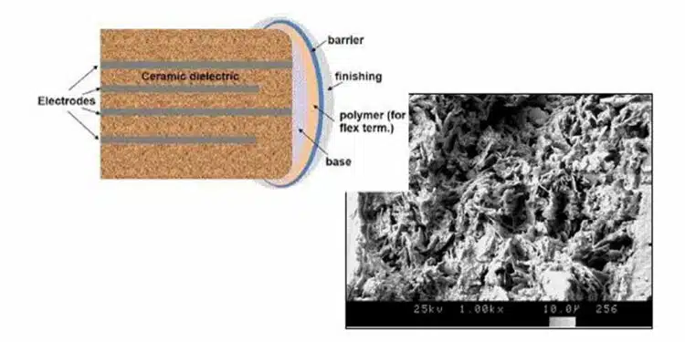
FlexiCap™ polymer termination with its fibrous structure effectively reduces the mechanical stress being exerted onto the ceramic section of the capacitor by approximately 50%. During FlexiCap trials, some 10 million polymer terminated Class II X7R (2R1) capacitors were supplied to customers for evaluation. The applications targeted were those known to have a long history of problems due to capacitor cracking. During the course of these trials, not a single part was identified to have failed as a result of chip fracture.

AEC-Q200 certified components terminated with FlexiCap™ have a higher resistance to mechanical cracking meeting the demand by electronic design engineers for components that far exceed the minimum industry standard for flexibility, enabling Knowles Precision Devices to offer a guaranteed 5mm bend test deflection on AEC-Q200 components exceeding all of the requirements touched on above.

Related

Source: Knowles Precision Devices

Recent Posts

Paumanok Releases Capacitor Foils Market Report 2025-2030

7.10.2025
1

Modelithics Welcomes CapV as a Sponsoring MVP

7.10.2025
1

Benefits of Tantalum Powder Stress–Strain Curve Evaluation vs Conventional Wet Test

3.10.2025
16

Electrolyte Selection and Performance in Supercapacitors

3.10.2025
16

Researchers Demonstrated High Energy Ceramic Capacitors Stable in Wide Temperature Range

2.10.2025
23

Stackpole Offers High Voltage Plate Resistors up to 40KV

2.10.2025
16

How to Manage Supercapacitors Leakage Current and Self Discharge 

1.10.2025
37

Qualification of Commercial Supercapacitors for Space Applications

1.10.2025
37

Experimental Evaluation of Wear Failures in SMD Inductors

1.10.2025
35

Resonant Capacitors in High-Power Resonant Circuits

1.10.2025
36

Upcoming Events

Oct 8
11:00 - 12:00 CEST

PCB Online Shop – simply “Made in Germany” by Würth Elektronik

Oct 14
16:00 - 17:00 CEST

Smart Sensors, Smarter AI: Building Reliable Edge Systems

Oct 17
12:00 - 14:00 EDT

External Visual Inspection per MIL-STD-883 TM 2009

Oct 20
October 20 - October 23

Digital WE Days 2025 – Virtual Conference

Oct 21
October 21 @ 12:00 - October 23 @ 14:15 EDT

Space and Military Standards for Hybrids and RF Microwave Modules

View Calendar

Popular Posts

  • Buck Converter Design and Calculation

    0 shares
    Share 0 Tweet 0
  • Boost Converter Design and Calculation

    0 shares
    Share 0 Tweet 0
  • Flyback Converter Design and Calculation

    0 shares
    Share 0 Tweet 0
  • LLC Resonant Converter Design and Calculation

    0 shares
    Share 0 Tweet 0
  • SEPIC Converter Design and Calculation

    0 shares
    Share 0 Tweet 0
  • Ripple Current and its Effects on the Performance of Capacitors

    3 shares
    Share 3 Tweet 0
  • Dual Active Bridge (DAB) Topology Explained

    0 shares
    Share 0 Tweet 0
  • What is a Dielectric Constant and DF of Plastic Materials?

    4 shares
    Share 4 Tweet 0
  • Flying Capacitors Explained

    0 shares
    Share 0 Tweet 0
  • MLCC and Ceramic Capacitors

    0 shares
    Share 0 Tweet 0

Newsletter Subscription


Passive Components Blog

© EPCI - Leading Passive Components Educational and Information Site

  • Home
  • Privacy Policy
  • EPCI Membership & Advertisement
  • About

No Result
View All Result
  • Home
  • Knowledge Blog
  • Premium Suppliers

© EPCI - Leading Passive Components Educational and Information Site

This website uses cookies. By continuing to use this website you are giving consent to cookies being used. Visit our Privacy and Cookie Policy.
Go to mobile version