Passive Components Blog
No Result
View All Result
  • Home
  • NewsFilter
    • All
    • Aerospace & Defence
    • Antenna
    • Applications
    • Automotive
    • Capacitors
    • Circuit Protection Devices
    • electro-mechanical news
    • Filters
    • Fuses
    • Inductors
    • Industrial
    • Integrated Passives
    • inter-connect news
    • Market & Supply Chain
    • Market Insights
    • Medical
    • Modelling and Simulation
    • New Materials & Supply
    • New Technologies
    • Non-linear Passives
    • Oscillators
    • Passive Sensors News
    • Resistors
    • RF & Microwave
    • Telecommunication
    • Weekly Digest

    YAGEO Releases Compact Coupled Inductors for High-Density VR Designs

    Enhancing Energy Density in Nanocomposite Dielectric Capacitors

    Advances in the Environmental Performance of Polymer Capacitors

    Vishay Releases DLA Tantalum Polymer Capacitors for Military and Aerospace

    Vishay Expanded Inductor Portfolio With More Than 2000 Stock Items 

    Paumanok Releases Capacitor Foils Market Report 2025-2030

    Modelithics Welcomes CapV as a Sponsoring MVP

    Wk 40 Electronics Supply Chain Digest

    Benefits of Tantalum Powder Stress–Strain Curve Evaluation vs Conventional Wet Test

    Trending Tags

    • Ripple Current
    • RF
    • Leakage Current
    • Tantalum vs Ceramic
    • Snubber
    • Low ESR
    • Feedthrough
    • Derating
    • Dielectric Constant
    • New Products
    • Market Reports
  • VideoFilter
    • All
    • Antenna videos
    • Capacitor videos
    • Circuit Protection Video
    • Filter videos
    • Fuse videos
    • Inductor videos
    • Inter-Connect Video
    • Non-linear passives videos
    • Oscillator videos
    • Passive sensors videos
    • Resistor videos

    Connector PCB Design Challenges

    Efficient Power Converters: Duty Cycle vs Conduction Losses

    Ripple Steering in Coupled Inductors: SEPIC Case

    SEPIC Converter with Coupled and Uncoupled Inductors

    Coupled Inductors in SEPIC versus Flyback Converters

    Non-Linear MLCC Class II Capacitor Measurements Challenges

    Percolation Phenomenon and Reliability of Molded Power Inductors in DC/DC converters

    Root Causes and Effects of DC Bias and AC in Ceramic Capacitors

    How to Calculate the Output Capacitor for a Switching Power Supply

    Trending Tags

    • Capacitors explained
    • Inductors explained
    • Resistors explained
    • Filters explained
    • Application Video Guidelines
    • EMC
    • New Products
    • Ripple Current
    • Simulation
    • Tantalum vs Ceramic
  • Knowledge Blog
  • Suppliers
    • Who is Who
  • Events
No Result
View All Result
Passive Components Blog
No Result
View All Result

High-Voltage Temperature Sensors for Connectors in e-Mobility; TDK App Note

29.12.2021
Reading Time: 3 mins read
A A

In e-mobility, the temperature of all system units needs to be constantly monitored. The high currents result in losses with a corresponding generation of heat arising, in particular, at contacts. TDK has now developed a special-purpose high-voltage resistant temperature sensor for connectors.

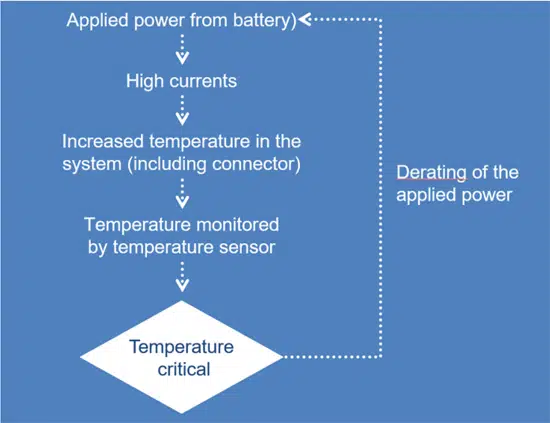
Today high-voltage batteries for electric vehicles (xEV) have rated voltages of up to 1000 V, necessitating all system components to be correspondingly high-voltage resistant. Currents in the three-digit bracket arise in achieving high drive power – some well over 100 kW – via inverter and motor. Together with line and contact resistances, these high currents result in substantial power dissipations and associated thermal losses since the currents are squared in the calculation: PV = I2 x R. This makes it clear that even slight resistances in the milliohm range produce relatively large losses and thus a possibly critical rise in temperature. If, for example, a contact point has a 10 mΩ resistance and is applied with a 100 A current, the result is a 100 W power dissipation which can quickly lead to overheating. That is why in xEV critical contact points – such as a connector between battery and motor inverter – must be thermally monitored and the current reduced in good time given imminent overheating. NTC-based temperature sensors which initiate current derating are suitable for monitoring the temperature at critical points. Figure 1 illustrates the control principle.

RelatedPosts

New EPN Dielectric Film Capacitors Featuring High Temp and Power Density

EMI Noise Mitigation in Automotive 48V Power Supply Systems

TDK Releases Industry-Leading 22nF 1000V C0G MLCCs in the 3225 Case

High requirements placed on NTC temperature sensors for xEV

Figure 1: Control principle of a temperature monitoring unit with corresponding current derating.

E-mobility places completely different requirements on developing and designing  NTC temperature sensors, especially for their integration into high volt systems. These include:

  • High-voltage resistance
  • Brief response time
  • High-temperature stability
  • High degree of precision
  • Scope for direct integration into connectors

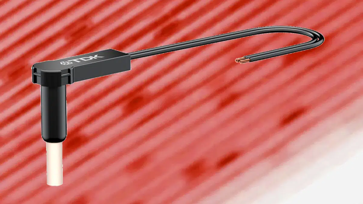
The challenge was finding a material with both a high electrical insulation property and, at the same time, excellent thermal conductivity and developing a design to integrate an NTC element. Furthermore, a high-temperature stability was to be provided. A special-purpose ceramic sleeve in which the sensor die is integrated proved to be suitable. Featured Image illustrates the temperature sensor developed in this way.

Innovative TDK temperature sensor meets all requirements

Multiple successful tests have proved that the newly-developed TDK temperature sensor meets the requirements placed on it. The high-voltage test produced a 5 kV DC dielectric strength of the sensor head – clearly well above the 1 kV DC system voltage. Also obtained was the required brief response time. It is particularly important for starting derating in good time given a case of sudden overheating. A τ-value (63%) of well under <10 s seconds was recorded in a typical installation situation. The permitted temperature range is -40 °C to +150 °C with brief 180 °C applications allowed.

Sensor precision is also an important aspect. Only when it is sufficiently high can derating be started not only in good time but also not too early on. At 25 °C, the new sensor has a maximum ±0.2 K deviation with the R25 resistance at 10 kΩ under a 1 percent tolerance.

The upper plastic section of the sensor is designed such that diverse customer fitting requirements, such as screw-on, clip-in or clip-on, can be implemented.

All in all, the effective electrical, thermal and mechanical values of the new sensor contribute to making electro-mobility safer and more efficient.

Related

Source: TDK

Recent Posts

Enhancing Energy Density in Nanocomposite Dielectric Capacitors

9.10.2025
9

Advances in the Environmental Performance of Polymer Capacitors

8.10.2025
19

Benefits of Tantalum Powder Stress–Strain Curve Evaluation vs Conventional Wet Test

3.10.2025
22

Electrolyte Selection and Performance in Supercapacitors

3.10.2025
19

Connector PCB Design Challenges

3.10.2025
22

Researchers Demonstrated High Energy Ceramic Capacitors Stable in Wide Temperature Range

2.10.2025
24

How to Manage Supercapacitors Leakage Current and Self Discharge 

1.10.2025
42

Experimental Evaluation of Wear Failures in SMD Inductors

1.10.2025
41

Resonant Capacitors in High-Power Resonant Circuits

1.10.2025
40
a Schematic diagram of the BNT-based components constructed based on the entropy-increase strategy. b Digital photograph, cross-sectional SEM image, and EDS mappings of the MLCCs. c Unipolar P-E loops of MLCCs as a function of applied E. d Wrec and η of the MLCCs as a function of applied E. The comparison of (e) Wrec and η, (f) η and UF of the MLCCs with those of other recently reported state-of-the-art MLCCs. source: Nature Communications

Researchers Proposed Enhanced Energy Storage MLCC

1.10.2025
19

Upcoming Events

Oct 14
16:00 - 17:00 CEST

Smart Sensors, Smarter AI: Building Reliable Edge Systems

Oct 17
12:00 - 14:00 EDT

External Visual Inspection per MIL-STD-883 TM 2009

Oct 20
October 20 - October 23

Digital WE Days 2025 – Virtual Conference

Oct 21
October 21 @ 12:00 - October 23 @ 14:15 EDT

Space and Military Standards for Hybrids and RF Microwave Modules

Oct 28
8:00 - 15:00 CET

Power Up Your Design: SN6507 and the Ready-to-Use Development Kit

View Calendar

Popular Posts

  • Buck Converter Design and Calculation

    0 shares
    Share 0 Tweet 0
  • Boost Converter Design and Calculation

    0 shares
    Share 0 Tweet 0
  • Flyback Converter Design and Calculation

    0 shares
    Share 0 Tweet 0
  • LLC Resonant Converter Design and Calculation

    0 shares
    Share 0 Tweet 0
  • What is a Dielectric Constant and DF of Plastic Materials?

    4 shares
    Share 4 Tweet 0
  • SEPIC Converter Design and Calculation

    0 shares
    Share 0 Tweet 0
  • Dual Active Bridge (DAB) Topology Explained

    0 shares
    Share 0 Tweet 0
  • Ripple Current and its Effects on the Performance of Capacitors

    3 shares
    Share 3 Tweet 0
  • MLCC and Ceramic Capacitors

    0 shares
    Share 0 Tweet 0
  • Flying Capacitors Explained

    0 shares
    Share 0 Tweet 0

Newsletter Subscription


Passive Components Blog

© EPCI - Leading Passive Components Educational and Information Site

  • Home
  • Privacy Policy
  • EPCI Membership & Advertisement
  • About

No Result
View All Result
  • Home
  • Knowledge Blog
  • Premium Suppliers

© EPCI - Leading Passive Components Educational and Information Site

This website uses cookies. By continuing to use this website you are giving consent to cookies being used. Visit our Privacy and Cookie Policy.
Go to mobile version