Passive Components Blog
No Result
View All Result
  • Home
  • NewsFilter
    • All
    • Aerospace & Defence
    • Antenna
    • Applications
    • Automotive
    • Capacitors
    • Circuit Protection Devices
    • electro-mechanical news
    • Filters
    • Fuses
    • Inductors
    • Industrial
    • Integrated Passives
    • inter-connect news
    • Market & Supply Chain
    • Market Insights
    • Medical
    • Modelling and Simulation
    • New Materials & Supply
    • New Technologies
    • Non-linear Passives
    • Oscillators
    • Passive Sensors News
    • Resistors
    • RF & Microwave
    • Telecommunication
    • Weekly Digest

    Samsung Electro-Mechanics Releases High-Capacitance MLCCs for AI Server Applications

    Samsung Electro-Mechanics Releases 165C Automotive 0806 Size Power Inductors

    Coupled Inductors Circuit Model and Examples of its Applications

    Würth Elektronik Introduces LTspice Models for ESD Products

    Capacitor Ripple Current Testing: A Design Consideration

    TDK Releases 0201 High-Frequency Smallest Inductors

    Coilcraft Extends Air Core RF Inductors

    Bourns Releases Automotive 1W Flyback Transformer

    Wk 20 Electronics Supply Chain Digest

    Trending Tags

    • Ripple Current
    • RF
    • Leakage Current
    • Tantalum vs Ceramic
    • Snubber
    • Low ESR
    • Feedthrough
    • Derating
    • Dielectric Constant
    • New Products
    • Market Reports
  • VideoFilter
    • All
    • Antenna videos
    • Capacitor videos
    • Circuit Protection Video
    • Filter videos
    • Fuse videos
    • Inductor videos
    • Inter-Connect Video
    • Non-linear passives videos
    • Oscillator videos
    • Passive sensors videos
    • Resistor videos

    Coupled Inductors Circuit Model and Examples of its Applications

    Inductor Resonances and its Impact to EMI

    Highly Reliable Flex Rigid PCBs, Würth Elektronik Webinar

    Causes of Oscillations in Flyback Converters

    How to design a 60W Flyback Transformer

    Modeling and Simulation of Leakage Inductance

    Power Inductor Considerations for AI High Power Computing – Vishay Video

    Coupled Inductors in Multiphase Boost Converters

    VPG Demonstrates Precision Resistor in Cryogenic Conditions

    Trending Tags

    • Capacitors explained
    • Inductors explained
    • Resistors explained
    • Filters explained
    • Application Video Guidelines
    • EMC
    • New Products
    • Ripple Current
    • Simulation
    • Tantalum vs Ceramic
  • Knowledge Blog
  • Suppliers
    • Who is Who
  • Events
No Result
View All Result
Passive Components Blog
No Result
View All Result

How Controlled Self-Healing of Power Film Capacitors Works and Compares with Aluminum Capacitors

8.11.2023
Reading Time: 7 mins read
A A

This article written by Kevin Cho, KYOCERA-AVX Corporation discusses the distinctions between aluminum electrolytic and metal film capacitors before considering some distinct advantages of film capacitors and the self-healing properties of metallized film capacitors.

Abstract:

In high voltage, high energy applications such as electric trains and solar power grids, the safety and reliability of capacitors are paramount.

RelatedPosts

Capacitor Ripple Current Testing: A Design Consideration

KYOCERA AVX Releases Compact High-Directivity Couplers

Kyocera Introducing SAW Filters for Implantable Medical and AED Applications

Catastrophic failures and associated explosions or fires are unacceptable. Just as importantly, service lifetime and predictability for optimizing up-time are critical to the product’s success.

Film capacitors with controlled self-healing are the ideal solution to these challenges and can be obtained in various sizes and technical specifications.

Energy Storage Capacitors

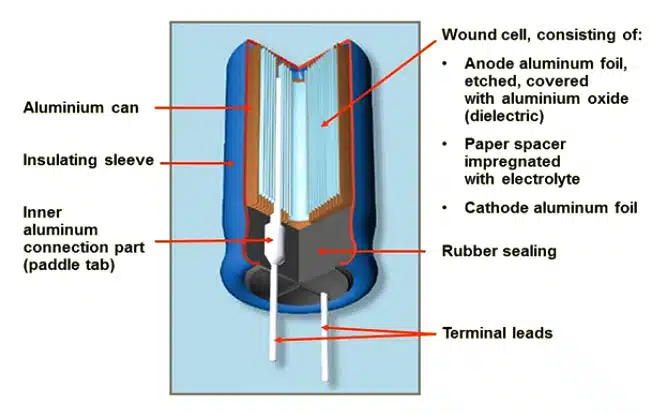
High voltage capacitors for energy storage are generally divided into two distinct technologies: aluminum electrolytic and metal film. Electrolytic capacitors rely on an aluminum oxide dielectric grown on aluminum foil electrodes to form the basic structure. These foils are wound and electrically contacted with an electrolyte-soaked paper separator, as shown in Figure 1.

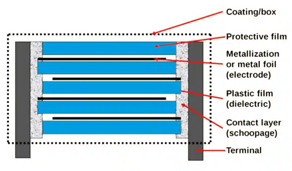
On the other hand, metal film capacitors rely on a metallized dielectric film to form the capacitive structure. Many film materials are available – most commonly, polypropylene and polyester. As shown in Figure 2, the metallized film is wound and contacted on either end to form an elementary capacitor, which is then stacked in series or parallel to realize higher voltage, higher-capacity devices.

Figure 1: Conventional aluminum electrolytic capacitor construction. Image courtesy of KYOCERA AVX.
Figure 2: Metal film capacitor structure. Image courtesy of KYOCERA AVX.

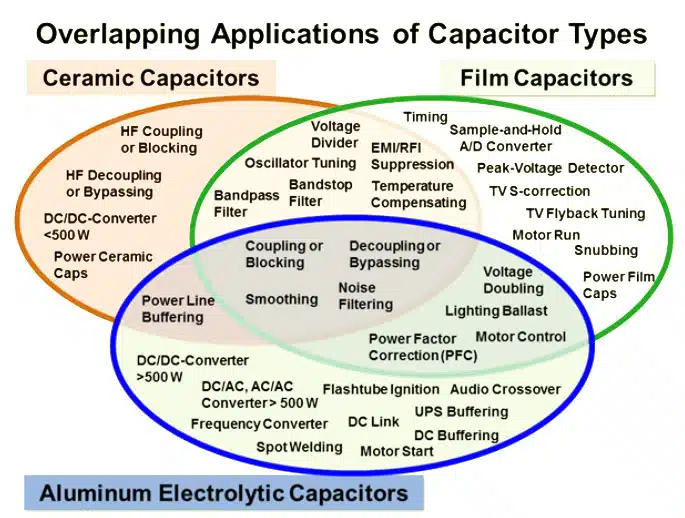
Aluminum electrolytics tend to be cost-effective in applications requiring high capacitance values at DC voltages less than 800V. These applications include DC-DC converters, motor starters, and frequency converters. When higher voltages are required, especially in non-polarized AC circuits, metal film capacitors are the only alternative option. Some example applications include sample and-hold circuits, snubbers, and peak voltage detectors.

However, as shown in Figure 3, both types of capacitors have tradeoffs that significantly overlap in their application spaces. For example, either capacitor may be used in lighting ballasts, noise filters, and DC blocking circuits depending on the design constraints.

Figure 3: Three primary capacitor technologies and their applications. Image courtesy of KYOCERA AVX

Film Capacitor Advantages

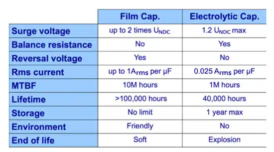
While aluminum electrolytic capacitors are a cost-effective solution in many designs, certain characteristic requirements may inhibit their use. The following table presents some critical parameters that may necessitate choosing a film capacitor for a particular application.

Current reversal, life-time, and end of life failure mode are three of the most critical parameters to consider. Current reversal is impossible in aluminum electrolytics because the oxide dielectric is initially grown on the aluminum electrodes via anodization. Reversing the voltage on such a structure results in a breakdown of the dielectric and eventual failure. Similarly, the overall lifetime and failure modes of aluminum electrolytics are
undesirable.

The oxide dielectric layer gradually breaks down, and the loss of electrolyte results in lower voltage tolerance and gas generation. Eventually, the device will fail in a short circuit condition and potentially explode or cause damage to supporting devices.

Table 1: Comparison of critical parameters between film and aluminum electrolytic capacitors. Image courtesy of KYOCERA AVX

Controlled Self-Healing

Figure 4: Basic self-healing process of film capacitors. Image courtesy of KYOCERA AVX.

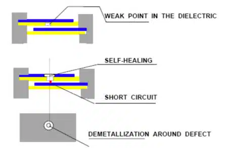
Metallized film capacitors exhibit a self-healing property that significantly improves their lifetime reliability characteristics. Figure 4 depicts the basic process wherein a dielectric defect results in a high current, high-temperature short circuit that quickly demetallizes the surrounding area.

Unfortunately, this mechanism can be difficult to control, and in the worst case, a run-away process can result, causing the destruction of the entire capacitor in short order. To avoid this, KYOCERA AVX developed a controlled self-healing process in 1974 based on the segmentation of overall capacitance into elementary cells protected by fuse gates.

A micrograph is shown in Figure 5a, where an elementary capacitive cell has experienced a defect, and the resulting overcurrent condition has broken all four of its fuses – Figure 5b. This isolates the defective cell without affecting the remainder of the capacitor. Also shown is the overall reduction of capacitance over time as more and more of these elementary cells go off-line.

This controlled self-healing technique is now the standard construction for all KYOCERA AVX’s film capacitor solutions, including dry, no free oil, and oil impregnated. As a result, these capacitors experience no catastrophic failure (short circuit). Just as importantly, the decrease in bulk capacitance over time is well modeled and directly measurable, allowing for an accurate prediction of capacitor lifetime and determination of an optimal service schedule.

Figure 5a: Example of metallized cell self-healed defect with fuse element broken
Figure 5b: Reduction of total capacitance with oxide degradation over time.

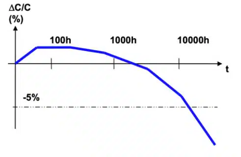
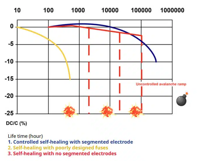
Figure 6 presents three lifetime curves of capacitance change to illustrate the point. The red line is the worst-case scenario with no self-healing strategy. The degradation is unpredictable and may result in a catastrophic failure. The yellow line uses a fused design for control, but the fuses are improperly sized for the elementary cell. The device fails prematurely through rapid loss of capacitance over time. The blue line presents the KYOCERA
AVX design, where decades of experience have yielded a design with no catastrophic failure and an extended, highly predictable lifetime.

Figure 6 : Comparison of capacitor lifetimes for different self-healing strategies. Image courtesy of KYOCERA AVX

KYOCERA AVX Capacitors for Reliable Self-Healing Protection

As of December 2020, KYOCERA AVX has delivered 8.6 million dry film capacitors with an estimated cumulative lifetime of 391 billion hours. Of these, there have been zero catastrophic failures. Such a track record of safety and reliability is unparalleled and speaks to design quality while validating the core self-healing technology.

Related

Source: KYOCERA AVX

Recent Posts

Samsung Electro-Mechanics Releases High-Capacitance MLCCs for AI Server Applications

21.5.2025
24

Coupled Inductors Circuit Model and Examples of its Applications

21.5.2025
14

Würth Elektronik Introduces LTspice Models for ESD Products

21.5.2025
14

Littelfuse Gate Driver Integrates Diode and Current Limit Resistor in Compact IC

21.5.2025
6

Capacitor Ripple Current Testing: A Design Consideration

21.5.2025
20

Coilcraft Extends Air Core RF Inductors

20.5.2025
9

Bourns Releases Automotive 1W Flyback Transformer

19.5.2025
13

Inductor Resonances and its Impact to EMI

16.5.2025
41

Developing Low Inductance Film Capacitor using Bode 100 Analyzer

15.5.2025
43

Highly Reliable Flex Rigid PCBs, Würth Elektronik Webinar

15.5.2025
24

Upcoming Events

May 28
16:00 - 17:00 CEST

Power Over Data Line

View Calendar

Popular Posts

  • Buck Converter Design and Calculation

    0 shares
    Share 0 Tweet 0
  • Boost Converter Design and Calculation

    0 shares
    Share 0 Tweet 0
  • Flyback Converter Design and Calculation

    0 shares
    Share 0 Tweet 0
  • LLC Resonant Converter Design and Calculation

    0 shares
    Share 0 Tweet 0
  • What is a Dielectric Constant and DF of Plastic Materials?

    4 shares
    Share 4 Tweet 0
  • Flying Capacitors Explained

    0 shares
    Share 0 Tweet 0
  • How to Design an Inductor

    0 shares
    Share 0 Tweet 0
  • SEPIC Converter Design and Calculation

    0 shares
    Share 0 Tweet 0
  • Capacitor Losses (ESR, IMP, DF, Q), Series or Parallel Eq. Circuit ?

    0 shares
    Share 0 Tweet 0
  • A Guide to Understanding Common Mode Choke

    0 shares
    Share 0 Tweet 0

Newsletter Subscription


Passive Components Blog

© EPCI - Leading Passive Components Educational and Information Site

  • Home
  • Privacy Policy
  • EPCI Membership & Advertisement
  • About

No Result
View All Result
  • Home
  • Knowledge Blog
  • Premium Suppliers

© EPCI - Leading Passive Components Educational and Information Site

This website uses cookies. By continuing to use this website you are giving consent to cookies being used. Visit our Privacy and Cookie Policy.
Go to mobile version