Passive Components Blog
No Result
View All Result
  • Home
  • NewsFilter
    • All
    • Aerospace & Defence
    • Antenna
    • Applications
    • Automotive
    • Capacitors
    • Circuit Protection Devices
    • electro-mechanical news
    • Filters
    • Fuses
    • Inductors
    • Industrial
    • Integrated Passives
    • inter-connect news
    • Market & Supply Chain
    • Market Insights
    • Medical
    • Modelling and Simulation
    • New Materials & Supply
    • New Technologies
    • Non-linear Passives
    • Oscillators
    • Passive Sensors News
    • Resistors
    • RF & Microwave
    • Telecommunication
    • Weekly Digest

    KYOCERA AVX Releases Hermaphroditic WTW and WTB Connectors

    Radiation Tolerance of Tantalum and Ceramic Capacitors

    TDK Releases Compact Polypropylene Film Capacitors for Resonant Topologies

    Percolation Phenomenon and Reliability of Molded Power Inductors in DC/DC converters

    Root Causes and Effects of DC Bias and AC in Ceramic Capacitors

    Würth Elektronik Offers Accessory Humidity Sensor Filter Cap

    Knowles Unveils High-Performance Safety-Certified MLCC Capacitors

    Vishay Releases High Saturation 180C Automotive Inductors

    How to Calculate the Output Capacitor for a Switching Power Supply

    Trending Tags

    • Ripple Current
    • RF
    • Leakage Current
    • Tantalum vs Ceramic
    • Snubber
    • Low ESR
    • Feedthrough
    • Derating
    • Dielectric Constant
    • New Products
    • Market Reports
  • VideoFilter
    • All
    • Antenna videos
    • Capacitor videos
    • Circuit Protection Video
    • Filter videos
    • Fuse videos
    • Inductor videos
    • Inter-Connect Video
    • Non-linear passives videos
    • Oscillator videos
    • Passive sensors videos
    • Resistor videos

    Percolation Phenomenon and Reliability of Molded Power Inductors in DC/DC converters

    Root Causes and Effects of DC Bias and AC in Ceramic Capacitors

    How to Calculate the Output Capacitor for a Switching Power Supply

    Switched Capacitor Converter Explained

    Understanding Inductor Dot Markings and Their Application in LTspice

    Accelerating Full Bridge LLC Resonant Converter Design with Frenetic AI

    Understanding Switched Capacitor Converters

    Coupled Inductors Circuit Model and Examples of its Applications

    Inductor Resonances and its Impact to EMI

    Trending Tags

    • Capacitors explained
    • Inductors explained
    • Resistors explained
    • Filters explained
    • Application Video Guidelines
    • EMC
    • New Products
    • Ripple Current
    • Simulation
    • Tantalum vs Ceramic
  • Knowledge Blog
  • Suppliers
    • Who is Who
  • Events
No Result
View All Result
Passive Components Blog
No Result
View All Result

How to Specify Capacitors for High-Energy Pulse Applications

12.12.2024
Reading Time: 4 mins read
A A

This article based on Knowles Precision Devices blog discusses how to specify capacitors for high-energy pulse applications.

Energy storage capacitor banks supply pulsed power in all manner of high-current applications, including shockless compression and fusion.

RelatedPosts

Knowles Unveils High-Performance Safety-Certified MLCC Capacitors

Knowles Releases Inductors for Mission-Critical RF Applications

Learn How Supercapacitors Enhance Power System in Knowles eBook

As the technology behind capacitor banks advances with more precise switching and higher energy density, fast discharge capacitors can reliably support more advanced applications.  

The energy storage capacitors selected for large banks must feature low inductance, high peak current, strong fault tolerance and excellent reliability over their lifespan.

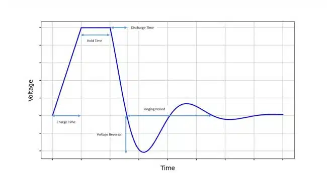
When working to specify high energy capacitors, consider the following charge, hold and discharge profile for a capacitor in an RLC circuit (Figure 1).

Figure 1: Hold and discharge profile for a capacitor in an RLC circuit 

The following questions address crucial factors that influence capacitor performance, reliability and longevity in high-energy pulse applications. Answering them will help us ensure that you have the right capacitors for your design. 

What capacitance and voltage conditions will your high energy capacitors be subjected to? 

By definition, the energy stored in a charged capacitor is: 

where

  • C is capacitance (F)
  • V is the charging voltage (V)

There are a few real-world factors that influence the mathematical relationship here. Depending on the charging method, achievable voltage varies. Further, capacitor discharge is never 100 percent efficient. Knowles Precision Devices is prepared to discuss your energy storage goals and help you establish capacitance and charging voltage targets. 

What’s your strategy for capacitor charging? 

Considering the amount of energy at play, power supply choice is an important design parameter. Regardless of the charging mode (e.g., constant voltage, constant current, constant power or resonant charging), shorter charge time is favorable to avoid prefiring. Figure 1 shows constant current charging time as the first stage in the hold and discharge profile. 

How long do you need the capacitor to hold its charge?

The second stage in the hold and discharge profile, shown in Figure 1, is the hold time. Account for this period in your design process as excessive hold times impact overall safety and reliability.

How quickly must the capacitor bank discharge its energy into the circuit? 

Discharge time is determined by RLC circuit parameters, so share as much as you can about the circuit the capacitor bank will discharge into. 

What is the expected ringing period, if any? 

The damping of the RLC circuit your capacitor bank is discharging into may cause voltage ringing. Share if you have specific design criteria around the ringing period. 

What is the expected voltage reversal? 

The expected voltage reversal is the reverse peak voltage that occurs during the pulse discharge process of the capacitor. Reversal happens due to the parasitic inductance in the circuit, which causes energy to oscillate between the capacitance and inductance. The oscillation causes a reverse voltage and current to briefly appear across the capacitor, such that it’s measurable at each pulse. Capacitors have different rated tolerances for reverse voltage. 

What is the desired shot life? 

Shot life, expressed as a percentage of survival probability, indicates the number of charge/discharge cycles that a capacitor can endure before failure. Capacitor lifespan depends on factors like the percentage voltage reversal, ringing frequency, temperature and operating voltage. Knowles Precision Devices offers statistical analyses to understand capacitor survival rates in context. 

What is the target pulse repetition rate?

The target pulse repetition rate should be set to achieve a reasonable shot life for the capacitor. In addition to selecting materials with high dielectric strength and low loss, depending on the target rate, specialized cooling methods might be needed for heat dissipation and mechanical reinforcement. 

In addition to a thorough understanding of the specs detailed here, it’s important to consider your form factor, as it imposes additional size constraints on capacitor selection.

Related

Source: Knowles Precision Devices

Recent Posts

Radiation Tolerance of Tantalum and Ceramic Capacitors

8.8.2025
24

TDK Releases Compact Polypropylene Film Capacitors for Resonant Topologies

7.8.2025
12

Percolation Phenomenon and Reliability of Molded Power Inductors in DC/DC converters

6.8.2025
18

Root Causes and Effects of DC Bias and AC in Ceramic Capacitors

6.8.2025
13

Knowles Unveils High-Performance Safety-Certified MLCC Capacitors

6.8.2025
21

How to Calculate the Output Capacitor for a Switching Power Supply

6.8.2025
17

Additive Manufacturing of Mn-Zn Ferrite Planar Inductors

4.8.2025
11

Evaluation and Modeling of Supercapacitors for Reliability of Lifetime Predictions

4.8.2025
20

Researchers Presents High-Performance Carbon-Based Supercapacitors

1.8.2025
24

Modelithics Announces v25.5 of the COMPLETE+3D Library for Ansys HFSS

1.8.2025
5

Upcoming Events

Sep 22
September 22 @ 13:00 - September 25 @ 15:15 EDT

Pre Cap Visual Inspection per Mil-Std-883 (TM 2017)

Sep 30
September 30 @ 12:00 - October 2 @ 14:00 EDT

MIL-Std-883 TM 2010

Oct 17
12:00 - 14:00 EDT

External Visual Inspection per MIL-STD-883 TM 2009

Oct 21
October 21 @ 12:00 - October 23 @ 14:15 EDT

Space and Military Standards for Hybrids and RF Microwave Modules

Nov 4
November 4 @ 12:00 - November 6 @ 14:15 EST

Wirebond Materials, Processes, Reliability and Testing

View Calendar

Popular Posts

  • Buck Converter Design and Calculation

    0 shares
    Share 0 Tweet 0
  • Boost Converter Design and Calculation

    0 shares
    Share 0 Tweet 0
  • Flyback Converter Design and Calculation

    0 shares
    Share 0 Tweet 0
  • LLC Resonant Converter Design and Calculation

    0 shares
    Share 0 Tweet 0
  • What is a Dielectric Constant and DF of Plastic Materials?

    4 shares
    Share 4 Tweet 0
  • Ripple Current and its Effects on the Performance of Capacitors

    3 shares
    Share 3 Tweet 0
  • Dual Active Bridge (DAB) Topology Explained

    0 shares
    Share 0 Tweet 0
  • How to Design an Inductor

    0 shares
    Share 0 Tweet 0
  • MLCC Case Sizes Standards Explained

    0 shares
    Share 0 Tweet 0
  • MLCC and Ceramic Capacitors

    0 shares
    Share 0 Tweet 0

Newsletter Subscription


Passive Components Blog

© EPCI - Leading Passive Components Educational and Information Site

  • Home
  • Privacy Policy
  • EPCI Membership & Advertisement
  • About

No Result
View All Result
  • Home
  • Knowledge Blog
  • Premium Suppliers

© EPCI - Leading Passive Components Educational and Information Site

This website uses cookies. By continuing to use this website you are giving consent to cookies being used. Visit our Privacy and Cookie Policy.
Go to mobile version