Passive Components Blog
No Result
View All Result
  • Home
  • NewsFilter
    • All
    • Aerospace & Defence
    • Antenna
    • Applications
    • Automotive
    • Capacitors
    • Circuit Protection Devices
    • electro-mechanical news
    • Filters
    • Fuses
    • Inductors
    • Industrial
    • Integrated Passives
    • inter-connect news
    • Market & Supply Chain
    • Market Insights
    • Medical
    • Modelling and Simulation
    • New Materials & Supply
    • New Technologies
    • Non-linear Passives
    • Oscillators
    • Passive Sensors News
    • Resistors
    • RF & Microwave
    • Telecommunication
    • Weekly Digest

    VINATech Targets AI Data Center Supercapacitor Boom

    Littelfuse NANO2 415 SMD Fuse Wins 2025 Product of the Year

    TDK Introduces 350V Safety Film Capacitors for Compact EMI Suppression

    Molex Extends Cardinal Multi‑Port Coax Assemblies to 145 GHz for AI and 6G Test

    Samsung Launches Worlds First Automotive 47uF 4V MLCC in 0805 Size

    Würth Elektronik Present in IEEE APEC

    Samsung Three Pillars MLCC Strategy for AI Hardware Topology

    Bourns Releases High Clearance Transformer for Isolated DC/DC Supplies

    KYOCERA AVX Extends Ultra‑Broadband RF Capacitor Series

    Trending Tags

    • Ripple Current
    • RF
    • Leakage Current
    • Tantalum vs Ceramic
    • Snubber
    • Low ESR
    • Feedthrough
    • Derating
    • Dielectric Constant
    • New Products
    • Market Reports
  • VideoFilter
    • All
    • Antenna videos
    • Capacitor videos
    • Circuit Protection Video
    • Filter videos
    • Fuse videos
    • Inductor videos
    • Inter-Connect Video
    • Non-linear passives videos
    • Oscillator videos
    • Passive sensors videos
    • Resistor videos

    2026 Power Magnetics Design Trends: Flyback, DAB and Planar

    Enabling Software‑Defined Vehicle Architectures: Automotive Ethernet and Zonal Smart Power

    Calculating Resistance Value of a Flyback RC Snubber 

    One‑Pulse Characterization of Nonlinear Power Inductors

    Thermistor Linearization Challenges

    Coaxial Connectors and How to Connect with PCB

    PCB Manufacturing, Test Methods, Quality and Reliability

    Transformer Behavior – Current Transfer and Hidden Feedback

    Choosing the Right Capacitor: The Importance of Accurate Measurements

    Trending Tags

    • Capacitors explained
    • Inductors explained
    • Resistors explained
    • Filters explained
    • Application Video Guidelines
    • EMC
    • New Products
    • Ripple Current
    • Simulation
    • Tantalum vs Ceramic
  • Knowledge Blog
  • DossiersNew
  • Suppliers
    • Who is Who
  • PCNS
    • PCNS 2025
    • PCNS 2023
    • PCNS 2021
    • PCNS 2019
    • PCNS 2017
  • Events
No Result
View All Result
Passive Components Blog
No Result
View All Result

How to Suppress Leakage Inductance in Transformer Design

10.10.2023
Reading Time: 7 mins read
A A

In this blog article Pablo Blázquez, Frenetic Power Εlectronics Εngineer is exploring a key element in Transformer design: the leakage inductance!

Leakage Inductance

Leakage inductance is produced by the imperfect magnetic coupling between the transformer windings. The magnetic flux generated in the primary winding is never transferred 100% to the secondary winding. Its magnitude plays a key role in modern switched-mode power supplies. Whether it needs to be minimized or maximized, the use of complex prediction models, which are many times far from reality, is required.

RelatedPosts

2026 Power Magnetics Design Trends: Flyback, DAB and Planar

Power Electronics Tools for Passives and Magnetic Designs

DC/DC Push‑Pull Converter vs PSFB Design Guide

In cases where higher leakage inductance is required, a magnetic shunt can be inserted between layers, while another possibility would be the use of fractional turns.

Leakage inductance depends on:

  • Winding geometry.
  • Core geometry.
  • Number of turns.

Due to the fact that the winding geometry and arrangement have a high influence on the leakage inductance, it gets really complicated to calculate it analytically and get reliable results. However, if you know the effect these parameters have on the leakage, you will be able to control it.

How to Reduce it?

Here are some solutions to reduce the leakage inductance:

  • Decreasing the number of turns and layers. 
  • Reducing the insulator layer thickness. 
  • Using the interleaving arrangement. 
  • Lowering the mean turn length. 
  • Increasing the core window width.
  • Decreasing the core window height.

The reduction of the leakage inductance is fundamental to obtain better power efficiency, but it goes at the expense of other parameters. For example, reducing the number of turns will also produce higher core losses. On the other hand, it is important to bear in mind the relationship between leakage inductance and parasitic capacitance: lower leakage inductances will lead to higher capacitances (C1= 1/w2 lk1).

In other cases, where higher leakage inductance is required, a magnetic shunt can be inserted between layers. Yet another possibility would be the use of fractional turns.

Experimental Results

Let’s analyse now several case studies with a focus on the leakage inductance. By changing the construction of our transformer and transformer topology, we’ll see what are the effects induced on the leakage inductance value.

Case Study 1: change construction parameters

In this experiment we can see how different cores, winding arrangement and number of turns, while keeping the turns ratio constant, influence the leakage inductance values:

  • Experiment 1: PQ26/25 transformer with a turns ratio of 2:1.
  • Experiment 2: PQ26/25 transformer with a turns ratio of 2:1 but the number of turns is half than in experiment 1. 
  • Experiment 3: PQ26/25 transformer with a turns ratio of 2:1 and P-S-S-P arrangement. 
  • Experiment 4: PQ26/20 transformer with a turns ratio of 2:1 and a P-S-S-P arrangement.
Figure 1. Case Study 1 Results

The results are summarized in Figure 1. Table.

For experiments 1 and 2 show how the reduction of the number of turns leads to a consequent decrease in the leakage inductance.

Comparing experiments 1 and 3, it is clear how the leakage changes when the primary and secondary wires are alternated. Experiments 3 and 4 show the effect of the change in the height of the window: higher core windows will have higher leakage inductances. 

Case Study 2: influence of the winding arrangement in different topologies

Let’s change now the winding arrangement in different topologies and see the effect of the leakage inductance.

Values of leakage inductance will be measured for different converters with four different winding configurations – see Figure 2., from the high-pot winding arrangement (Conf. 1) to two layers interleaving arrangement (Conf. 4) passing through simple P-S configuration (Conf. 2) and simple interleaving (Conf. 3).

Figure 2. Transformer winding arrangement configurations used for the measurements
Table 1. Data of the different converters used in the experiment

Table 1 shows the Converters used for this experiment for each topology with different winding configurations. Results demonstrate how the smaller the difference between primary and secondary turns, and the better the interleaving arrangement, the smaller the leakage inductance achieved.

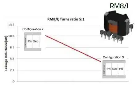
Case Study 2: Experiment 1

Figure 3 shows how the leakage inductance is reduced by 50% from Conf. 1 to Conf. 3 in an RM8/I. The more the winding is interleaved, the lower the leakage.

Minimization of the leakage inductance in flyback Converters is generally a must, otherwise high voltage spikes at the switching node would be present with the increased stress that this involves in the semiconductors. The interleaved planar Transformer could be used in this case, but taking a special care of the parasitic capacitance that will create a path for common-mode noise.

Figure 3. Leakage inductance in two RM8/I with a turns ratio of 5:1
Figure 4. Leakage inductance in two PQ40/40 with a turns ratio of 8:1

Case Study 2: Experiment 2

In experiment 2, we used a PQ40/40 with a turn ratio of 1:1. The Llk is reduced by a factor of 4. The decrease in the leakage inductance appears as a consequence of the division of the winding on a higher number of layers with interleaving arrangement, from P-S to P-S-P-S arrangement. 

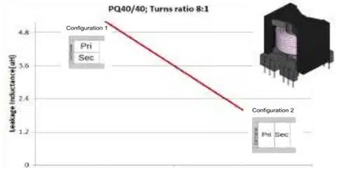
Case Study 2: Experiment 3

Experiment 3 in Figure 4. uses the same core shape as in case 2, but with 8 times higher turns ratio (8:1). Winding Conf. 1 and 2 do not seem very different, however, as we can see in the results, the Llk is reduced 2.6 times, from 5.2 to 2 uH.

Compared to experiment 2, it seems to have lower Llk change. But talking in absolute values, it has a higher impact, as in experiment 2 the leakage is reduced 0.6 uH, and in experiment 7 is of 3.2 uH. 

Conclusions

Knowing the leakage inductance in advance can give you an idea of the total efficiency of the magnetic component before manufacturing it. Theoretical calculations can give you an approach to the leakage inductance of a planar Transformer, but calculations become much harder and less accurate when it is not a planar.

Here is what I’ve learned from this experiment:

  • When turns ratio is closer to 1, we have better coupling between windings and leakage below 1uH.
  • Winding arrangement has a great influence on leakage results.
  • Knowing the leakage value can help you create more efficient designs.

By using Frenetic you can get accurate results of the leakage inductance in your design in a matter of seconds. This will help you further optimize your design and reduce the time you need for designing magnetics.

Related

Source: Frenetic

Recent Posts

Würth Elektronik Present in IEEE APEC

24.2.2026
15

Bourns Releases High Clearance Transformer for Isolated DC/DC Supplies

24.2.2026
8

Earthing Systems and IEC Classification Explained

26.2.2026
18

Bourns Extends Multilayer Chip Inductors Offer for RF and Wireless Designs

20.2.2026
14

Würth Elektronik Component Data Live in Accuris

19.2.2026
17

Coilcraft Releases Automotive Common Mode Chokes

19.2.2026
21

2026 Power Magnetics Design Trends: Flyback, DAB and Planar

13.2.2026
74

Vishay Releases Compact 0806 Low‑DCR Power Inductor

5.2.2026
37

Murata Publishes Power Delivery Guide for AI Servers

4.2.2026
135

Upcoming Events

Mar 3
16:00 - 17:00 CET

Cybersecurity at the Eleventh Hour – from RED to CRA – Information and Discussion

Mar 21
All day

PSMA Capacitor Workshop 2026

Apr 21
16:00 - 17:00 CEST

Heatsink Solutions: Thermal Management in electronic devices

View Calendar

Popular Posts

  • Buck Converter Design and Calculation

    0 shares
    Share 0 Tweet 0
  • Boost Converter Design and Calculation

    0 shares
    Share 0 Tweet 0
  • Flyback Converter Design and Calculation

    0 shares
    Share 0 Tweet 0
  • LLC Resonant Converter Design and Calculation

    0 shares
    Share 0 Tweet 0
  • MLCC Manufacturers Consider Price Increase as AI Demand Outpaces Supply

    0 shares
    Share 0 Tweet 0
  • Dual Active Bridge (DAB) Topology

    0 shares
    Share 0 Tweet 0
  • Ripple Current and its Effects on the Performance of Capacitors

    3 shares
    Share 3 Tweet 0
  • What is a Dielectric Constant and DF of Plastic Materials?

    4 shares
    Share 4 Tweet 0
  • MLCC and Ceramic Capacitors

    0 shares
    Share 0 Tweet 0
  • MLCC Case Sizes Standards Explained

    0 shares
    Share 0 Tweet 0

Newsletter Subscription


Passive Components Blog

© EPCI - Leading Passive Components Educational and Information Site

  • Home
  • Privacy Policy
  • EPCI Membership & Advertisement
  • About

No Result
View All Result
  • Home
  • Knowledge Blog
  • PCNS

© EPCI - Leading Passive Components Educational and Information Site

This website uses cookies. By continuing to use this website you are giving consent to cookies being used. Visit our Privacy and Cookie Policy.
Go to mobile version