Passive Components Blog
No Result
View All Result
  • Home
  • NewsFilter
    • All
    • Aerospace & Defence
    • Antenna
    • Applications
    • Automotive
    • Capacitors
    • Circuit Protection Devices
    • electro-mechanical news
    • Filters
    • Fuses
    • Inductors
    • Industrial
    • Integrated Passives
    • inter-connect news
    • Market & Supply Chain
    • Market Insights
    • Medical
    • Modelling and Simulation
    • New Materials & Supply
    • New Technologies
    • Non-linear Passives
    • Oscillators
    • Passive Sensors News
    • Resistors
    • RF & Microwave
    • Telecommunication
    • Weekly Digest

    VINATech Targets AI Data Center Supercapacitor Boom

    Littelfuse NANO2 415 SMD Fuse Wins 2025 Product of the Year

    TDK Introduces 350V Safety Film Capacitors for Compact EMI Suppression

    Molex Extends Cardinal Multi‑Port Coax Assemblies to 145 GHz for AI and 6G Test

    Samsung Launches Worlds First Automotive 47uF 4V MLCC in 0805 Size

    Würth Elektronik Present in IEEE APEC

    Samsung Three Pillars MLCC Strategy for AI Hardware Topology

    Bourns Releases High Clearance Transformer for Isolated DC/DC Supplies

    KYOCERA AVX Extends Ultra‑Broadband RF Capacitor Series

    Trending Tags

    • Ripple Current
    • RF
    • Leakage Current
    • Tantalum vs Ceramic
    • Snubber
    • Low ESR
    • Feedthrough
    • Derating
    • Dielectric Constant
    • New Products
    • Market Reports
  • VideoFilter
    • All
    • Antenna videos
    • Capacitor videos
    • Circuit Protection Video
    • Filter videos
    • Fuse videos
    • Inductor videos
    • Inter-Connect Video
    • Non-linear passives videos
    • Oscillator videos
    • Passive sensors videos
    • Resistor videos

    2026 Power Magnetics Design Trends: Flyback, DAB and Planar

    Enabling Software‑Defined Vehicle Architectures: Automotive Ethernet and Zonal Smart Power

    Calculating Resistance Value of a Flyback RC Snubber 

    One‑Pulse Characterization of Nonlinear Power Inductors

    Thermistor Linearization Challenges

    Coaxial Connectors and How to Connect with PCB

    PCB Manufacturing, Test Methods, Quality and Reliability

    Transformer Behavior – Current Transfer and Hidden Feedback

    Choosing the Right Capacitor: The Importance of Accurate Measurements

    Trending Tags

    • Capacitors explained
    • Inductors explained
    • Resistors explained
    • Filters explained
    • Application Video Guidelines
    • EMC
    • New Products
    • Ripple Current
    • Simulation
    • Tantalum vs Ceramic
  • Knowledge Blog
  • DossiersNew
  • Suppliers
    • Who is Who
  • PCNS
    • PCNS 2025
    • PCNS 2023
    • PCNS 2021
    • PCNS 2019
    • PCNS 2017
  • Events
No Result
View All Result
Passive Components Blog
No Result
View All Result

Impulse-Controlled Sequential Switch Without Active Electronics

23.1.2019
Reading Time: 4 mins read
A A

Source: Electronic Design news

by Marek Irek, Technical Manager at the Relcon Polska. This circuit uses two electromechanical relays to realize a sequential switch that’s permanently resistant to electrical disturbance, remembering its state despite power failure and consuming energy only when it’s switched from one state to the other.

RelatedPosts

VINATech Targets AI Data Center Supercapacitor Boom

Littelfuse NANO2 415 SMD Fuse Wins 2025 Product of the Year

TDK Introduces 350V Safety Film Capacitors for Compact EMI Suppression

I know, I know—discussing the subject of a relay-based sequence switch in the age of omnipresent microprocessors seems to be a waste of time. After all, relays have been in use for many years. Is it possible to create something new from these already well-known relays? I tried many years ago, and I think that I succeeded.

I admit that this project is late by about 70 years, but I think its clarity of structure and operation deserves some attention. The first thing that makes it stand out is the fact that despite executing the function of a logic circuit, it does not use active electronic elements. In addition, despite the simple structure, it possesses features of much more complex digital systems.

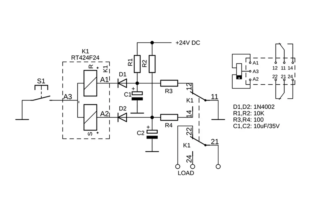
The sequence switch, built on two-coil bi-stable relays, is partially a development of the article “Relay-Based ON/OFF Flip-Flop Remembers State During Power Failure.” In that Idea for Design article, the author, Tommy Tyler, presented a relay-based flip-flop circuit, the trigger concept of which is quite similar to my idea submitted to the Polish Patent Office over 20 years ago (Featured image Fig. 1 above).

featured image Fig.1.: This pulse-controlled circuit of a dual-coil bi-stable relay performs an ON/OFF function, remembers the state during power failure, and is permanently jam-proof. Component values aren’t critical.

This design was created due to the need for an effective current switch triggered by a pulse that remembers the state during a supply failure and is permanently resistant to disruptions. The main idea was to use the fact that coils of bi-stable relay at rest do not require a power supply, allowing for the accumulation of an electric charge that can switch the relay.

Because accumulated charge should have an appropriate polarization and alternately power the relay coils, I’ve used one pole of relay contacts as a switching key. It allows current to flow unidirectionally through the excited coil and block for the duration of pulse triggering of the passive coil. Despite the fact that the same control pulse is provided to both coils, only one of them is able to create an electromagnetic field thanks to this configuration, enabling the relay contacts to switch into position opposite to the currently occupied one.

When mobile contacts will be transferred into the other stable position by the charge flowing through chosen coil, the low potential present on the central connect—mutual for both coil—prevents the accumulation of charge necessary to power the other coil until the input is opened. Even its temporary opening allows for an accumulation of charge sufficient to trigger it at the moment the control pulse reappears.

Triggering coils in such a way makes it possible to build a bi-stable flip-flop trigger or one based on two such latches like the sequence switch in Figure 2. The flip-flop circuit built according to the idea described above (Fig. 1, again) during standby mode consumes a current of several milliamps, which in certain circumstances can be considered as a disadvantage.

2. This simple, pulse-controlled system of two dual-coil bi-stable relays performs the function of a sequential switch. A unique feature of the switch is that it performs without active electronics components, remembers the state during power failure, is permanently jam-proof, and consumes no power except when it switches from one state to the other. Component values aren’t critical.

In his project, Mr. Tyler proposed a more economic method of powering the circuit storing the charge, thanks to the latch consuming virtually no current during standby (if we skip the leakage of capacitors). The main operation concept remained the same; thus, all advantages described earlier, as well as the limits mentioned in that article, can be fully referenced to the sequence switch circuit presented here.

Its unique features permanently resist disruptions and power failure, remember state during power failure, don’t consume power during standby, and have only a short, impulse consumption at the moment of charging the capacitor and triggering. The switch presented here, after each press of the S1 momentary trigger button, executes a sequence of switch-overs: [Activate M1] > [Deactivate M1] > [Activate M2] > [Deactivate M2] > [Activate M1], etc. Therefore, it can be used to switch drives operating in such a cycle, e.g., drives of gates or roller blinds.

In the schematic (Fig. 2, again), the two sets of contacts of these relays (pins 11, 12, and 14) are used to control flip-flops. The remaining two K1 and K2 sets (pins 21, 22, and 24) are used to switch the voltage powering the electric load ON and OFF. The middle exits of the A3 coils for both relays (K1 and K2), which are connected to each other, constitute as a mutual control entry of the switch—it’s activated by temporarily shorting the circuit ground of the S1 button.

Because switch-over cycles of both latches are synchronized with each other, but a quantity of cyles are different, free contacts set themselves into a sequence of connections. This makes it possible to control the M1 and M2 loads as described above.

The system is very tolerant in terms of the components used. You can use two-coil bi-stable relays with various rated voltages. You only need to select the appropriate value of capacitor that allow enough energy to switch a relay. It’s easy to do by checking whether the selected capacitor charged with the relay’s rated voltage is able to switch it after being connected to the coil.

The value of resistors is not critical either. Increasing the resistance value will cause the restriction of switching frequency; decreasing it will result in more frequent and more dynamic reactions. However, when reducing the resistance, you should remember that at the moment control switch S1 is closed to the ground on the blocked coil, there should be a voltage smaller than the relay trigger voltage.

Related

Recent Posts

VINATech Targets AI Data Center Supercapacitor Boom

26.2.2026
5

Littelfuse NANO2 415 SMD Fuse Wins 2025 Product of the Year

26.2.2026
4

TDK Introduces 350V Safety Film Capacitors for Compact EMI Suppression

26.2.2026
4

Würth Elektronik Present in IEEE APEC

24.2.2026
14

Samsung Three Pillars MLCC Strategy for AI Hardware Topology

24.2.2026
33

Bourns Releases High Clearance Transformer for Isolated DC/DC Supplies

24.2.2026
8

Bourns Unveils High Volt GDT for High‑Energy Surge Protection

23.2.2026
4

TDK Releases DC Link Aluminum Capacitors for EV On‑Board Chargers

23.2.2026
16

Capacitech C-Link Supercapacitors for AI Data Center Voltage Spikes Mitigation

23.2.2026
28

Upcoming Events

Mar 3
16:00 - 17:00 CET

Cybersecurity at the Eleventh Hour – from RED to CRA – Information and Discussion

Mar 21
All day

PSMA Capacitor Workshop 2026

Apr 21
16:00 - 17:00 CEST

Heatsink Solutions: Thermal Management in electronic devices

View Calendar

Popular Posts

  • Buck Converter Design and Calculation

    0 shares
    Share 0 Tweet 0
  • Boost Converter Design and Calculation

    0 shares
    Share 0 Tweet 0
  • Flyback Converter Design and Calculation

    0 shares
    Share 0 Tweet 0
  • LLC Resonant Converter Design and Calculation

    0 shares
    Share 0 Tweet 0
  • MLCC Manufacturers Consider Price Increase as AI Demand Outpaces Supply

    0 shares
    Share 0 Tweet 0
  • Dual Active Bridge (DAB) Topology

    0 shares
    Share 0 Tweet 0
  • Ripple Current and its Effects on the Performance of Capacitors

    3 shares
    Share 3 Tweet 0
  • What is a Dielectric Constant and DF of Plastic Materials?

    4 shares
    Share 4 Tweet 0
  • MLCC and Ceramic Capacitors

    0 shares
    Share 0 Tweet 0
  • MLCC Case Sizes Standards Explained

    0 shares
    Share 0 Tweet 0

Newsletter Subscription


Passive Components Blog

© EPCI - Leading Passive Components Educational and Information Site

  • Home
  • Privacy Policy
  • EPCI Membership & Advertisement
  • About

No Result
View All Result
  • Home
  • Knowledge Blog
  • PCNS

© EPCI - Leading Passive Components Educational and Information Site

This website uses cookies. By continuing to use this website you are giving consent to cookies being used. Visit our Privacy and Cookie Policy.
Go to mobile version