Passive Components Blog
No Result
View All Result
  • Home
  • NewsFilter
    • All
    • Aerospace & Defence
    • Antenna
    • Applications
    • Automotive
    • Capacitors
    • Circuit Protection Devices
    • electro-mechanical news
    • Filters
    • Fuses
    • Inductors
    • Industrial
    • Integrated Passives
    • inter-connect news
    • Market & Supply Chain
    • Market Insights
    • Medical
    • Modelling and Simulation
    • New Materials & Supply
    • New Technologies
    • Non-linear Passives
    • Oscillators
    • Passive Sensors News
    • Resistors
    • RF & Microwave
    • Telecommunication
    • Weekly Digest

    Top 10 Connector Vendors by Product Type

    Bourns Releases High‑Q Air Coil Inductors for RF Aplications

    CMSE 2026 Announces Call for Presentations on High-Reliability Military and Space Electronics

    ESA Call for Papers 6th Space Passive Component Days – SPCD 2026

    Würth Elektronik Offers Halogen‑Free EMC Gaskets for Displays and Housings

    Component Distribution Supply Chain January 2026

    Binder Unveils M8 Flange Solder Connectors for Flexible Cabling

    Power Electronics Tools for Passives and Magnetic Designs

    Modelithics Releases Component Model Library for SIMULIA CST Studio Suite

    Trending Tags

    • Ripple Current
    • RF
    • Leakage Current
    • Tantalum vs Ceramic
    • Snubber
    • Low ESR
    • Feedthrough
    • Derating
    • Dielectric Constant
    • New Products
    • Market Reports
  • VideoFilter
    • All
    • Antenna videos
    • Capacitor videos
    • Circuit Protection Video
    • Filter videos
    • Fuse videos
    • Inductor videos
    • Inter-Connect Video
    • Non-linear passives videos
    • Oscillator videos
    • Passive sensors videos
    • Resistor videos

    One‑Pulse Characterization of Nonlinear Power Inductors

    Thermistor Linearization Challenges

    Coaxial Connectors and How to Connect with PCB

    PCB Manufacturing, Test Methods, Quality and Reliability

    Transformer Behavior – Current Transfer and Hidden Feedback

    Choosing the Right Capacitor: The Importance of Accurate Measurements

    RF Inductors: Selection and Design Challenges for High-Frequency Circuits

    Transformer Safety IEC 61558 Standard

    3-Phase EMI Filter Design, Simulation, Calculation and Test

    Trending Tags

    • Capacitors explained
    • Inductors explained
    • Resistors explained
    • Filters explained
    • Application Video Guidelines
    • EMC
    • New Products
    • Ripple Current
    • Simulation
    • Tantalum vs Ceramic
  • Knowledge Blog
  • DossiersNew
  • Suppliers
    • Who is Who
  • PCNS
    • PCNS 2025
    • PCNS 2023
    • PCNS 2021
    • PCNS 2019
    • PCNS 2017
  • Events
No Result
View All Result
Passive Components Blog
No Result
View All Result

Magnetic Induction, Magnetic Flux and Faraday’s Law

2.5.2025
Reading Time: 6 mins read
A A

The article defines the other basic principles of magnetism, magnetic and inductor components – Magnetic Induction, Magnetic Flux and Faraday’s Law.

Magnetic induction B

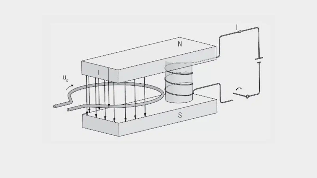
A potential is induced in a conductor loop if the magnetic field passing through the conductor loop changes with time.

RelatedPosts

One‑Pulse Characterization of Nonlinear Power Inductors

Transformer Behavior – Current Transfer and Hidden Feedback

Current Sense Transformer and its Calculation

The surge in potential over the area of the loop is known as the magnetic induction B. Like the magnetic field strength, the magnetic induction B is a vector quantity.

The following relationship applies for the magnetic induction B:

magnetic induction equation [1]

The magnetic induction (B) is the quotient of the induced potential surge:

potential induced magnetic surge [2]

and the product of the winding turns (N) and the windings area (A) of the induction coil.

The unit of magnetic induction (B) is the Tesla (T) = Vs/m2.

The magnetic induction B and the field strength H are proportional to one another. The constant of proportionality is the magnetic field constant (μ0), given by experimental measurement.

magnetic field constant [3]

In vacuum and also with sufficient accuracy for air, this leads to:

magnetic induction equation [4]

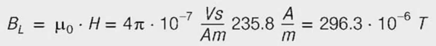
The magnetic induction (BL) in air for the above example is then given by:

magnetic induction in air environment [5]

Magnetic Flux F

The magnetic flux (F) is the scalar product of the magnetic flux density (B) and the area vector (dA).

magnetic flux equation [6]


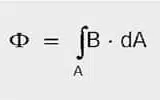
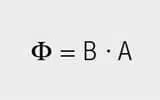
If (B) passes perpendicular through the area and the field is homogeneous:

magnetic flux equation in homogeneous field [7]


The unit of magnetic flux (F) is the same as that of the voltage surge (Vs) (Voltsecond) or Weber (Wb).

Faraday’s law

Up until now we have considered static magnetic fields. If the magnetic flux changes with time, a voltage U is induced (Faraday’s law).
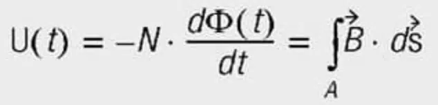
induced voltage Faradys Law [8]

U = induced voltage
t = time

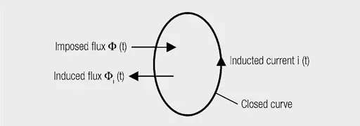
The polarity of the voltage is such that a current is generated on closing a circuit whose induced magnetic field opposes the original magnetic flux, i.e. it tends to reduce the magnetic field (Lenz’s rule – Figure 1.).

Figure 1. Representation of Lenz’s rule. The imposed magnetic field induces a current in the direction such that its induced magnetic field opposes the imposed field

Taking a winding with N turns, Faraday’s law can be expressed in the following form.

Faraday law with N turns winding [9]

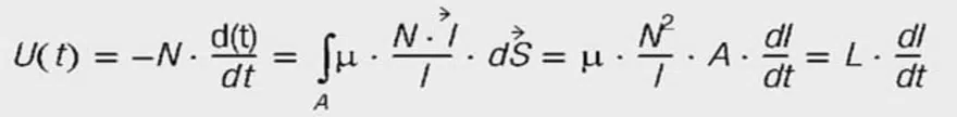
A = cross section of the coil
l = length of the coil or of the magnetic circuit
I = current through the coil
L = inductance of the coil [H(enry) = Vs/A]

So the inductance limits the change in current once a voltage is applied. It can be calculated from the coil data:

coil inductance equation [10]

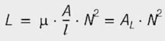
AL = AL value; mostly in nH/N2

The energy stored in the magnetic field is subject to the following relationships:

energy stored in magnetic field equation [11]


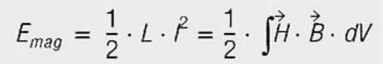
The energy stored in the volume V is composed of both the magnetic field strength H and the magnet flux density B. For transformers and chokes with ferromagnetic cores, the flux density is limited by saturation and is constant throughout the magnetic circuit. If an air gap is introduced (material with permeability μ~1), the field strength is highest in this air gap with H = B/μ. It follows that the energy density is highest in the air gap. One also speaks of the energy being stored in the air gap.

Related

Recent Posts

Bourns Releases High‑Q Air Coil Inductors for RF Aplications

29.1.2026
23

CMSE 2026 Announces Call for Presentations on High-Reliability Military and Space Electronics

28.1.2026
33

ESA Call for Papers 6th Space Passive Component Days – SPCD 2026

28.1.2026
24

Power Electronics Tools for Passives and Magnetic Designs

27.1.2026
65

Würth Elektronik Developed a Custom Transformer for Active Hand Orthosis

26.1.2026
38

Passive Components in Quantum Computing

22.1.2026
130

Exxelia Offers Custom Naval Transformers and Inductors

21.1.2026
16

Würth Elektronik Introduces Product Navigator for Passive Components

14.1.2026
90

Panasonic Passive Components for Reliable Robotic Arms

14.1.2026
116

Upcoming Events

Feb 24
16:00 - 17:00 CET

Designing Qi2 Wireless Power Systems: Practical Development and EMC Optimization

Mar 3
16:00 - 17:00 CET

Cybersecurity at the Eleventh Hour – from RED to CRA – Information and Discussion

Mar 21
All day

PSMA Capacitor Workshop 2026

View Calendar

Popular Posts

  • Buck Converter Design and Calculation

    0 shares
    Share 0 Tweet 0
  • Boost Converter Design and Calculation

    0 shares
    Share 0 Tweet 0
  • LLC Resonant Converter Design and Calculation

    0 shares
    Share 0 Tweet 0
  • Flyback Converter Design and Calculation

    0 shares
    Share 0 Tweet 0
  • Ripple Current and its Effects on the Performance of Capacitors

    3 shares
    Share 3 Tweet 0
  • How Metal Prices Are Driving Passive Component Price Hikes

    0 shares
    Share 0 Tweet 0
  • MLCC and Ceramic Capacitors

    0 shares
    Share 0 Tweet 0
  • Dual Active Bridge (DAB) Topology

    0 shares
    Share 0 Tweet 0
  • What is a Dielectric Constant and DF of Plastic Materials?

    4 shares
    Share 4 Tweet 0
  • Degradation of Capacitors and its Failure Mechanisms

    0 shares
    Share 0 Tweet 0

Newsletter Subscription


Passive Components Blog

© EPCI - Leading Passive Components Educational and Information Site

  • Home
  • Privacy Policy
  • EPCI Membership & Advertisement
  • About

No Result
View All Result
  • Home
  • Knowledge Blog
  • PCNS

© EPCI - Leading Passive Components Educational and Information Site

This website uses cookies. By continuing to use this website you are giving consent to cookies being used. Visit our Privacy and Cookie Policy.
Go to mobile version