Passive Components Blog
No Result
View All Result
  • Home
  • NewsFilter
    • All
    • Aerospace & Defence
    • Antenna
    • Applications
    • Automotive
    • Capacitors
    • Circuit Protection Devices
    • electro-mechanical news
    • Filters
    • Fuses
    • Inductors
    • Industrial
    • Integrated Passives
    • inter-connect news
    • Market & Supply Chain
    • Market Insights
    • Medical
    • Modelling and Simulation
    • New Materials & Supply
    • New Technologies
    • Non-linear Passives
    • Oscillators
    • Passive Sensors News
    • Resistors
    • RF & Microwave
    • Telecommunication
    • Weekly Digest

    Exxelia Exhibit at Electronica India September 17–19, 2025

    Würth Elektronik Announces 2025 Digital WE Days Virtual Conference

    VINATech Unveils Hybrid Energy Storage System to Revolutionize Grid Stability and Power Delivery

    SCHURTER Releases High Performance EV-Fuse

    Panasonic Industry to Double Production of MEGTRON PCB Materials

    5th PCNS Awards Outstanding Passive Component Papers

    TDK Releases Ultra-small PFC Capacitors

    KYOCERA AVX Releases Novel Mini BME Stacked Ceramic Capacitors

    Vishay Releases Class 1 Leaded High Voltage Ceramic Disc Capacitors

    Trending Tags

    • Ripple Current
    • RF
    • Leakage Current
    • Tantalum vs Ceramic
    • Snubber
    • Low ESR
    • Feedthrough
    • Derating
    • Dielectric Constant
    • New Products
    • Market Reports
  • VideoFilter
    • All
    • Antenna videos
    • Capacitor videos
    • Circuit Protection Video
    • Filter videos
    • Fuse videos
    • Inductor videos
    • Inter-Connect Video
    • Non-linear passives videos
    • Oscillator videos
    • Passive sensors videos
    • Resistor videos

    Ripple Steering in Coupled Inductors: SEPIC Case

    SEPIC Converter with Coupled and Uncoupled Inductors

    Coupled Inductors in SEPIC versus Flyback Converters

    Non-Linear MLCC Class II Capacitor Measurements Challenges

    Percolation Phenomenon and Reliability of Molded Power Inductors in DC/DC converters

    Root Causes and Effects of DC Bias and AC in Ceramic Capacitors

    How to Calculate the Output Capacitor for a Switching Power Supply

    Switched Capacitor Converter Explained

    Understanding Inductor Dot Markings and Their Application in LTspice

    Trending Tags

    • Capacitors explained
    • Inductors explained
    • Resistors explained
    • Filters explained
    • Application Video Guidelines
    • EMC
    • New Products
    • Ripple Current
    • Simulation
    • Tantalum vs Ceramic
  • Knowledge Blog
  • Suppliers
    • Who is Who
  • Events
No Result
View All Result
Passive Components Blog
No Result
View All Result

Inductors with Core Feature Multiple Resonances

29.3.2019
Reading Time: 3 mins read
A A

Source: InCompliance article

by Arturo Mediano. Resonances in components are a well-known topic for electronic designers when working in high frequencies (e.g. EMI/EMC). Do not forget to test your components with an impedance analyzer, especially if they are custom magnetic components.

RelatedPosts

Exxelia Exhibit at Electronica India September 17–19, 2025

Würth Elektronik Announces 2025 Digital WE Days Virtual Conference

VINATech Unveils Hybrid Energy Storage System to Revolutionize Grid Stability and Power Delivery

Designers working in high frequencies know that impedance of components as a function of frequency is not ideal. This is critical when trying to design circuits in high frequencies as for example in RF wireless systems or EMI/EMC design.

First, when learning circuit theory fundamentals, you work with capacitances, inductances, resistances, etc. Then, when trying to build your circuits you replace those ideal elements with capacitors, inductors, resistors, etc.

If the real component is equivalent to the ideal element, the circuit will work as expected from theory. But, if the component behavior is not ideal you can obtain unexpected results and you need to find a more complex model for it.

In Figure 1 you can see a typical plot (measure) of the impedance of a capacitor and an inductor. The response of a real capacitor is not ideal (Figure 1, left) and, at self-resonant frequency SRF=1.18MHz (phase 0º) the capacitor switches from an ideal capacitive response (1/ωC) to an inductive response (ωL) because the parasitics in the component.

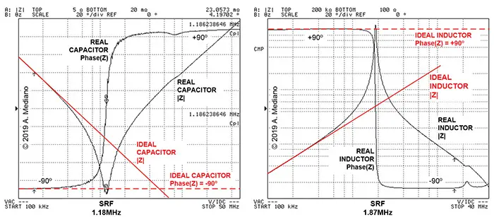
Figure 1: Impedance of a capacitor (left) and an inductor (right). (C) A.Mediano.

The response of a real inductor is not ideal (Figure 1, right), at self-resonant frequency SRF=1.87MHz (phase 0º) the inductor switches from an ideal inductive response (ωL) to a capacitive response (1/ωC) because the parasitics in the component.

That is because, when designing RF/EMI circuits (filters, decoupling networks, etc.) we consider typical series and parallel equivalent resonant circuits (Figure 2).

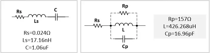
Figure 2: Typical model for a capacitor (left) and for an inductor (right).

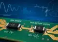
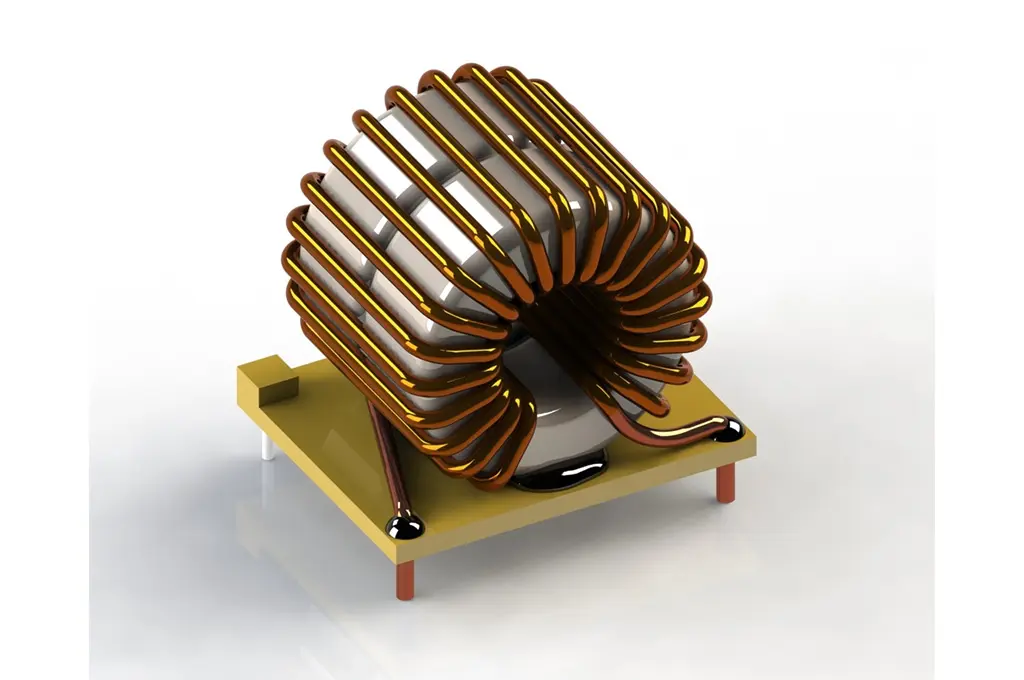
A very interesting case is found in many inductors with core as the ones used in power electronic circuits with stacked cores and multi-wire cable (Figure 3): transformers, power factor corrector circuits, EMC filters, etc.

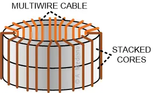
Figure 3: A typical inductor with stacked cores and multi-wire cable (C) A.Mediano

The response of impedance in frequency for those inductors offers several resonances as shown in Figure 4. Note that the component offers several resonant frequencies (not only one).

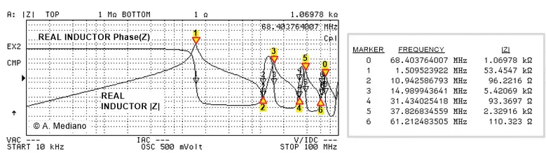
Figure 4: Typical response for one inductor with stacked cores and multi-wire cable. (C) A.Mediano

For the designer, it is difficult to model the component because several series and parallel resonant circuits will be needed to reproduce that behavior (a real complex model). Some designers use s-parameters to model the component but be careful with non-linearity as saturation. Why are those resonances dangerous?

Because for EMI/EMC, inductors are used many times in series (low pass filters, PFC inductor, etc.). The idea is to offer low impedance at low frequencies and high impedance at high frequencies.

But, if you think in resonances for markers 2, 4 and 6, at those frequencies the component offers low impedance (“short circuit”) so you will find an increase in emissions at those frequencies. In our example 10.9MHz, 31.4MHz, and 61.2MHz

If you do not measure the response of your inductor in your impedance analyzer, it will be difficult to understand why the emissions are especially bad at those frequencies.

The situation can be solved in several ways, for example, changing the inductor, replacing the cores with cores with losses in those frequencies (resonances will be with low Q), to modify the winding strategy, etc.

My final advice: test your inductors with stacked cores to compare emissions with their resonant frequencies. Sometimes you will be surprised with that comparison.

featured image source: Spanged Engineered Solutions


Arturo Mediano received his M.Sc. (1990) and his Ph. D. (1997) in Electrical Engineering from University of Zaragoza (Spain), where he has held a teaching professorship in EMI/EMC/RF/SI from 1992. From 1990, he has been involved in R&D projects in EMI/EMC/SI/RF fields for communications, industry and scientific/medical applications with a solid experience in training, consultancy and troubleshooting for companies in Spain, USA, Switzerland, France, UK, Italy, Belgium, Germany, Canada, The Netherlands, Portugal, and Singapore. He is the founder of The HF-Magic Lab®, a specialized laboratory for design, diagnostic, troubleshooting, and training in the EMI/EMC/SI and RF fields at I3A (University of Zaragoza), and from 2011, he is instructor for Besser Associates (CA, USA) offering public and on site courses in EMI/EMC/SI/RF subjects through the USA, especially in Silicon Valley/San Francisco Bay Area. He is Senior Member of the IEEE, active member from 1999 (Chair 2013-2016) of the MTT-17 (HF/VHF/UHF) Technical Committee of the Microwave Theory and Techniques Society and member of the Electromagnetic Compatibility Society


Related

Recent Posts

Exxelia Exhibit at Electronica India September 17–19, 2025

15.9.2025
8

Würth Elektronik Announces 2025 Digital WE Days Virtual Conference

15.9.2025
2

5th PCNS Awards Outstanding Passive Component Papers

14.9.2025
16
source: Samtec

Best Practices for Cable Management in High-Speed and High-Density Systems

4.9.2025
17

Würth Elektronik Unveils Compact Common-Mode Data Lines Chokes

3.9.2025
31

Bourns Releases Automotive High Creepage and Clearance Transformer

1.9.2025
31

Bourns Unveils Metal Powder Core High Current Low DCR Shielded Power Inductor

29.8.2025
38

Influence of Tantalum Capacitor Pellets Size on Stability During Oxide Film Formation

29.8.2025
44

Modelithics Release Discrete Components Optimization Article for RF/Microwave Designers

28.8.2025
15

Ripple Steering in Coupled Inductors: SEPIC Case

27.8.2025
25

Upcoming Events

Sep 16
17:00 - 18:00 CEST

EMI Shielding Challenges

Sep 22
September 22 @ 13:00 - September 25 @ 15:15 EDT

Pre Cap Visual Inspection per Mil-Std-883 (TM 2017)

Sep 30
September 30 @ 12:00 - October 2 @ 14:00 EDT

MIL-Std-883 TM 2010

Oct 17
12:00 - 14:00 EDT

External Visual Inspection per MIL-STD-883 TM 2009

Oct 20
October 20 - October 23

Digital WE Days 2025 – Virtual Conference

View Calendar

Popular Posts

  • Buck Converter Design and Calculation

    0 shares
    Share 0 Tweet 0
  • Boost Converter Design and Calculation

    0 shares
    Share 0 Tweet 0
  • Flyback Converter Design and Calculation

    0 shares
    Share 0 Tweet 0
  • LLC Resonant Converter Design and Calculation

    0 shares
    Share 0 Tweet 0
  • Dual Active Bridge (DAB) Topology Explained

    0 shares
    Share 0 Tweet 0
  • Ripple Current and its Effects on the Performance of Capacitors

    3 shares
    Share 3 Tweet 0
  • What is a Dielectric Constant and DF of Plastic Materials?

    4 shares
    Share 4 Tweet 0
  • SEPIC Converter Design and Calculation

    0 shares
    Share 0 Tweet 0
  • How to Design an Inductor

    0 shares
    Share 0 Tweet 0
  • Core Materials, Permeability and Their Losses

    0 shares
    Share 0 Tweet 0

Newsletter Subscription


Passive Components Blog

© EPCI - Leading Passive Components Educational and Information Site

  • Home
  • Privacy Policy
  • EPCI Membership & Advertisement
  • About

No Result
View All Result
  • Home
  • Knowledge Blog
  • Premium Suppliers

© EPCI - Leading Passive Components Educational and Information Site

This website uses cookies. By continuing to use this website you are giving consent to cookies being used. Visit our Privacy and Cookie Policy.
Go to mobile version