Passive Components Blog
No Result
View All Result
  • Home
  • NewsFilter
    • All
    • Aerospace & Defence
    • Antenna
    • Applications
    • Automotive
    • Capacitors
    • Circuit Protection Devices
    • electro-mechanical news
    • Filters
    • Fuses
    • Inductors
    • Industrial
    • Integrated Passives
    • inter-connect news
    • Market & Supply Chain
    • Market Insights
    • Medical
    • Modelling and Simulation
    • New Materials & Supply
    • New Technologies
    • Non-linear Passives
    • Oscillators
    • Passive Sensors News
    • Resistors
    • RF & Microwave
    • Telecommunication
    • Weekly Digest

    Wk 40 Electronics Supply Chain Digest

    Benefits of Tantalum Powder Stress–Strain Curve Evaluation vs Conventional Wet Test

    Electrolyte Selection and Performance in Supercapacitors

    Connector PCB Design Challenges

    Researchers Demonstrated High Energy Ceramic Capacitors Stable in Wide Temperature Range

    Stackpole Offers High Voltage Plate Resistors up to 40KV

    How to Manage Supercapacitors Leakage Current and Self Discharge 

    Qualification of Commercial Supercapacitors for Space Applications

    Experimental Evaluation of Wear Failures in SMD Inductors

    Trending Tags

    • Ripple Current
    • RF
    • Leakage Current
    • Tantalum vs Ceramic
    • Snubber
    • Low ESR
    • Feedthrough
    • Derating
    • Dielectric Constant
    • New Products
    • Market Reports
  • VideoFilter
    • All
    • Antenna videos
    • Capacitor videos
    • Circuit Protection Video
    • Filter videos
    • Fuse videos
    • Inductor videos
    • Inter-Connect Video
    • Non-linear passives videos
    • Oscillator videos
    • Passive sensors videos
    • Resistor videos

    Connector PCB Design Challenges

    Efficient Power Converters: Duty Cycle vs Conduction Losses

    Ripple Steering in Coupled Inductors: SEPIC Case

    SEPIC Converter with Coupled and Uncoupled Inductors

    Coupled Inductors in SEPIC versus Flyback Converters

    Non-Linear MLCC Class II Capacitor Measurements Challenges

    Percolation Phenomenon and Reliability of Molded Power Inductors in DC/DC converters

    Root Causes and Effects of DC Bias and AC in Ceramic Capacitors

    How to Calculate the Output Capacitor for a Switching Power Supply

    Trending Tags

    • Capacitors explained
    • Inductors explained
    • Resistors explained
    • Filters explained
    • Application Video Guidelines
    • EMC
    • New Products
    • Ripple Current
    • Simulation
    • Tantalum vs Ceramic
  • Knowledge Blog
  • Suppliers
    • Who is Who
  • Events
No Result
View All Result
Passive Components Blog
No Result
View All Result

IPC Class 2 vs Class 3 Solder Joints Requirements Explained

27.2.2025
Reading Time: 5 mins read
A A

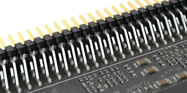
In this post, inspired by the Samtec blog, we’ll briefly examine IPC-A-610 Class 2 and Class 3 J-lead and Gull Wing solder joints, along with their respective requirements.

In the manufacturing world there are standards for just about everything, and they all are typically there to ensure a product can perform as expected for the end application. Among these standards is IPC-A-610 covering solder joints for varying types of connector termination styles.

RelatedPosts

Connector PCB Design Challenges

Samtec Agreed with Molex Second-Source License on High-Speed Interconnects for Data Centers

Best Practices for Cable Management in High-Speed and High-Density Systems

What is IPC-A-610

IPC-A-610 delves into the concept of “Acceptability of Electronic Assemblies,” and for the purpose of this blog, we will specifically focus on the requirements for J-Lead and Gull Wing solder connections. Considering the diverse applications that necessitate varying requirements, IPC has established different classes, each specifying the aesthetic characteristics of solder joints that must conform to those class specifications.

Class 2 

J-Lead Components

IPC-A-610 Class 2 is the standard requirement for J-lead component termination soldering. Class 2 products need extended reliability, but it’s not a critical requirement. We’ll cover some of the requirements below, but not all of them.

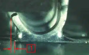
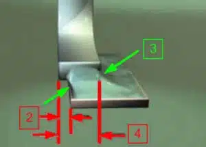
Class 2 allows the manufacturer more room for imperfections in the assembly, such as a larger toe offset (1) and side overhang (2), and a thinner end joint width (3) as shown in Figures 1 and 2 below. For side overhang, Class 2 states that the component lead may overhang the side of the pad (2), a maximum of 50% the width of the lead.

The end joint width (3) is the width of the solder joint at the most narrow point and must be a minimum of 50% of the lead width (4).

Figure 1. solder joint toe offset
Figure 2. solder joint side overhang, joint width and lead width

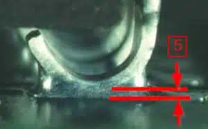
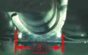
The solder thickness (5) between the lead and the pad landing is not specified, but a properly wetted fillet must be present. The side joint length (6) of the solder joint, at the narrowest point, must be at least 150% the width of the lead (4).

Figure 3. solder joint thickness
Figure 4. solder joint length

Class 2 is typically focused on a commercial type of product where continued performance and extended life is required, and an uninterrupted service of the product is desired but not mission critical. The normal environment (temperature and contamination) for this end user is not considered extreme.

Gull Wing Components

Because Class 2 provides the manufacturer a larger degree of imperfection in the solder joint, it is easier to manufacture at this level and often cheaper to produce. An example of this is the “pad offset” or the overhang of the contact from the pad. The Toe Overhang is defined in similar way as shown in Figure 1 for J-lead also for Gull Wing termination style, and is acceptable as long as it does not violate electrical clearance. This also means there is no requirement for a Toe Filet. The Side Overhang is shown in Figure 2., and Joint Width is also measured as is shown in (3) on the same figure.

Side Overhang (2), for Class 2, states a component lead may overhang the side of the land (contact pad) with a maximum of 50% the lead width(4), or 0.02 in. (0.5 mm), whichever is less. End Joint Width (3) is the width of the solder joint at the most narrow point. This width must be a minimum of 50% the width of the lead (4) . 

Side Joint Length (6) for a “long foot,” or a Lead Foot Length (5) that is equal to or greater than three lead widths (4), the Side Joint Length (6) must be a minimum of 3 (4) or 75% of (5); which ever is the longer of the two.

Class 3

J-Lead Components

Many high-reliability components and connectors can meet IPC-A-610 Class 3, which is usually required when a product must maintain high performance in extreme or harsh conditions. Military, aerospace, and medical applications typically require Class 3 products.

Class 3 imposes stricter inspection requirements for solder joints compared to Class 2. While the solder thickness (5) remains unchanged, the side joint length (6) is the same as Class 2. However, several other specifications have increased requirements.

For instance, the side overhang (2) and end joint width (3) are both tightened by 25% in both directions. The side overhang is limited to a maximum of 25% of the lead width (4), while the end joint thickness (3) is increased to a minimum of 75% of the lead width (4). Although this may not appear to be a significant increase, it does pose challenges in producing conforming products.

Gull Wing Components

Some requirements are similar in Class 2 and Class 3; such as the Solder Joint Length (6) and Toe Overhang (1). However, many of requirements are significantly more difficult to meet in a Class 3 solder joint.

End Joint Width (3) and Side Overhang (2), are both required to meet a more stringent specification. The End Joint (3) must be at least 75% of the lead width (4), and the Side Overhang (2) only affords the lead width (4) a maximum 25% of the lead width (4) or 0.02 in. (0.5 mm), whichever is less of overhang on the side of land.

Related

Source: Samtec

Recent Posts

Benefits of Tantalum Powder Stress–Strain Curve Evaluation vs Conventional Wet Test

3.10.2025
14

Electrolyte Selection and Performance in Supercapacitors

3.10.2025
13

Connector PCB Design Challenges

3.10.2025
16

Researchers Demonstrated High Energy Ceramic Capacitors Stable in Wide Temperature Range

2.10.2025
22

Stackpole Offers High Voltage Plate Resistors up to 40KV

2.10.2025
15

How to Manage Supercapacitors Leakage Current and Self Discharge 

1.10.2025
34

Qualification of Commercial Supercapacitors for Space Applications

1.10.2025
34

Experimental Evaluation of Wear Failures in SMD Inductors

1.10.2025
34

Resonant Capacitors in High-Power Resonant Circuits

1.10.2025
33
a Schematic diagram of the BNT-based components constructed based on the entropy-increase strategy. b Digital photograph, cross-sectional SEM image, and EDS mappings of the MLCCs. c Unipolar P-E loops of MLCCs as a function of applied E. d Wrec and η of the MLCCs as a function of applied E. The comparison of (e) Wrec and η, (f) η and UF of the MLCCs with those of other recently reported state-of-the-art MLCCs. source: Nature Communications

Researchers Proposed Enhanced Energy Storage MLCC

1.10.2025
16

Upcoming Events

Oct 8
11:00 - 12:00 CEST

PCB Online Shop – simply “Made in Germany” by Würth Elektronik

Oct 14
16:00 - 17:00 CEST

Smart Sensors, Smarter AI: Building Reliable Edge Systems

Oct 17
12:00 - 14:00 EDT

External Visual Inspection per MIL-STD-883 TM 2009

Oct 20
October 20 - October 23

Digital WE Days 2025 – Virtual Conference

Oct 21
October 21 @ 12:00 - October 23 @ 14:15 EDT

Space and Military Standards for Hybrids and RF Microwave Modules

View Calendar

Popular Posts

  • Buck Converter Design and Calculation

    0 shares
    Share 0 Tweet 0
  • Boost Converter Design and Calculation

    0 shares
    Share 0 Tweet 0
  • Flyback Converter Design and Calculation

    0 shares
    Share 0 Tweet 0
  • LLC Resonant Converter Design and Calculation

    0 shares
    Share 0 Tweet 0
  • SEPIC Converter Design and Calculation

    0 shares
    Share 0 Tweet 0
  • Ripple Current and its Effects on the Performance of Capacitors

    3 shares
    Share 3 Tweet 0
  • Dual Active Bridge (DAB) Topology Explained

    0 shares
    Share 0 Tweet 0
  • What is a Dielectric Constant and DF of Plastic Materials?

    4 shares
    Share 4 Tweet 0
  • Flying Capacitors Explained

    0 shares
    Share 0 Tweet 0
  • MLCC and Ceramic Capacitors

    0 shares
    Share 0 Tweet 0

Newsletter Subscription


Passive Components Blog

© EPCI - Leading Passive Components Educational and Information Site

  • Home
  • Privacy Policy
  • EPCI Membership & Advertisement
  • About

No Result
View All Result
  • Home
  • Knowledge Blog
  • Premium Suppliers

© EPCI - Leading Passive Components Educational and Information Site

This website uses cookies. By continuing to use this website you are giving consent to cookies being used. Visit our Privacy and Cookie Policy.
Go to mobile version