


by Wilmer Companioni. Decoupling and filtering are two of the main capacitor functionality circuit type. The following article by Kemet explains the basic considerations and selection guide for choosing the right capacitors.
Introduction
Decoupling and filtering are two sides of the same coin. Like most things engineering, it is the subtleties of use that determine the ultimate function. It is the reactive nature of capacitors that enable them to act as filtering and decoupling elements. Their impedance changes as a function of frequency.
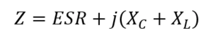
The capacitive reactance, Xc, is itself the capacitor’s portion of the frequency-dependent element of impedance, as shown below.
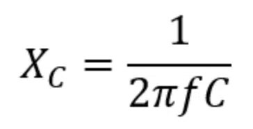
The impedance is larger at lower frequencies, which means that high frequency signals pass through these elements easier. This is beneficial for both decoupling and filtering applications, but in slightly different ways.
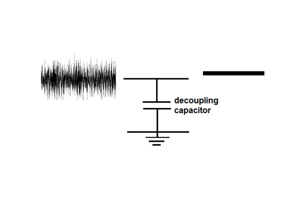
Decoupling
Decoupling capacitors act as local energy reservoirs to prevent the IC from experiencing a voltage drop. This is useful when multiple parts of the circuit are pulling from the same power supply at the same time, and they cannot all be supported. This prevents RC delays that could be caused from the voltage drooping. With decoupling capacitors, the different stages in the circuit do not have to wait to receive the power that they need because there is an extra supply held by the capacitor. Ideal circuit design is one the uses small value capacitors to handle short-term, fast transients and larger value capacitors for slower transients.
Choosing the right capacitor(s)
Choosing the right capacitor for decoupling is the next step. Since decoupling capacitors are going to allow the noise that lies near the self-resonant frequency to pass, it is valuable to know the frequency of the noise. This solution can be a single capacitor, or several capacitors placed in a bank. When choosing capacitors to place in a bank, there are two options; multiples of the same capacitor or different values. Using the first of these two methods widens the impedance bandwidth, reduces the ESR, and lowers the physical inductance. Using the link below will take you to KEMET’s KSIM tool which can allow you to compare the ESR/impedance of different capacitors or using several capacitors together in parallel.
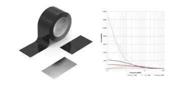
Figure 1 compares the ESR and impedance of 1 (top right plot), 10 (middle plot), and 100 (bottom left plot) of the same capacitors placed in parallel.
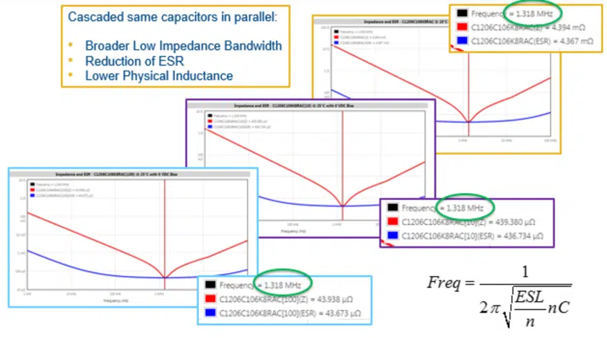
The bandwidth decreases and widens as more capacitors are added and since each capacitor has an ESR and inductance aspect, the combined ESR and inductance also decreases as more are added in parallel. It should be noted that equal capacitors in parallel does not alter the series resonant frequency.
Cascading different capacitors has the same effects as previously mentioned. The difference lies in widening the low impedance bandwidth. By adding different capacitors in parallel, the curve does not keep its same shape but can maintain a lower ESR at a larger range of frequencies as shown in Figure 2.
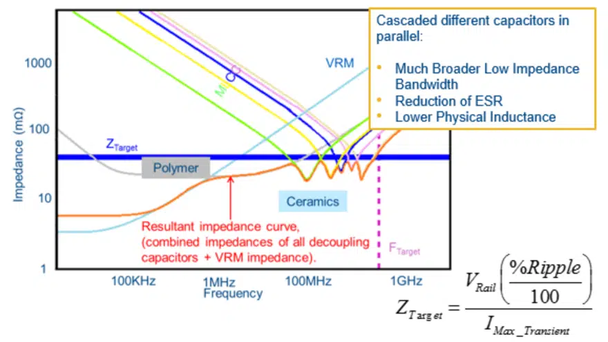
The important parameter to be aware of is the target impedance across the desired frequencies. The formula in Figure 2 can help calculate the target impedance specific to the application parameters. Since different parts have various self-resonant frequencies, adding different parts in parallel will keep the impedance low depending on their self-resonant frequency values.
KSIM
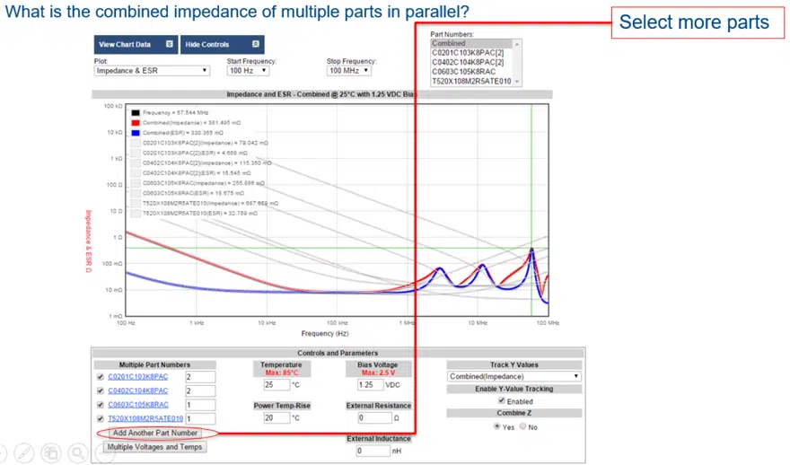
Click here to access KSIM and enter in the parts you would like to put in parallel. Add more parts using the Add Another Part Number at the bottom left of the page, see Figure 3.
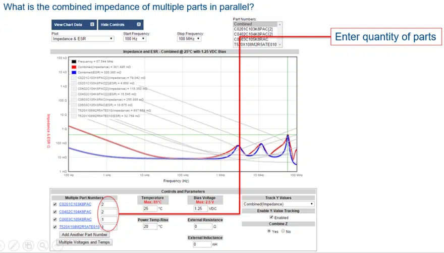
Use the numbers next to the part number to increase the quantity instead of entering in the same part twice if you choose to use multiple of the same part.
When you have all the parts you wish to use, check the Yes box under Calculate Z on the bottom right and click on Combined at the top right under the Part Numbers header.
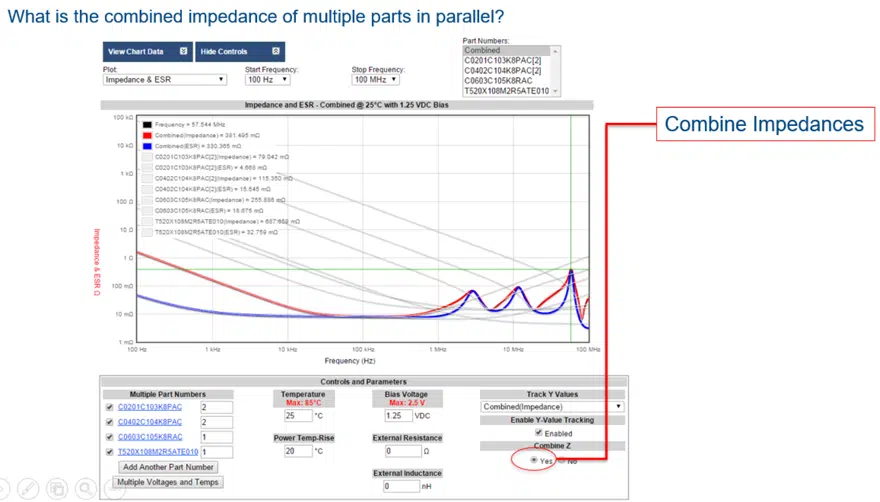
This will give you the projected impedance and ESR plots across a range of frequencies. You can also note the Controls and Parameters box at the bottom which will let you specify the temperatures and bias voltage that your application may have.
Filtering
Filtering capacitors are those that pass desired frequencies forward to other stages of the circuit while attenuating unwanted frequencies. These capacitors should be placed near the output of the stages of the circuit. Depending on how the capacitors are placed in the circuit, they can filter higher or lower frequencies. A series connection will pass high frequencies to the following stage while a parallel connection will shunt the high frequencies to ground allowing the lower frequencies to pass into the following stage.
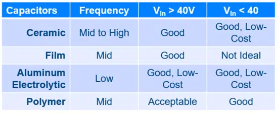
Choosing the right capacitor(s)
Table 1 will help in choosing which dielectric to begin with. Matching the self-resonant frequency of the capacitor with the switching frequency of the circuit will maximize the efficiency. You can do this by using the KSIM tool that was shown previously.
Conclusion
Decoupling and filtering are two of the most common uses of capacitors. It can be tempting to use the two terms interchangeably but in doing so, some of the key elements of usage can be overlooked. Decoupling is when capacitors are used as on-demand energy supplies for voltage transients of various lengths. Filtering is the practice of blocking or permitting frequencies in circuit stages. Whether decoupling or filtering, KEMET has the solutions necessary for both. Visit our simulation tool K-SIM to investigate capacitor behavior and visit ComponentEdge to find the capacitor right for you.