Passive Components Blog
No Result
View All Result
  • Home
  • NewsFilter
    • All
    • Aerospace & Defence
    • Antenna
    • Applications
    • Automotive
    • Capacitors
    • Circuit Protection Devices
    • electro-mechanical news
    • Filters
    • Fuses
    • Inductors
    • Industrial
    • Integrated Passives
    • inter-connect news
    • Market & Supply Chain
    • Market Insights
    • Medical
    • Modelling and Simulation
    • New Materials & Supply
    • New Technologies
    • Non-linear Passives
    • Oscillators
    • Passive Sensors News
    • Resistors
    • RF & Microwave
    • Telecommunication
    • Weekly Digest

    TDK Extends SMT Gate Drive Transformers to 1000 V

    Non-Linear MLCC Class II Capacitor Measurements Challenges

    Researchers Demonstrated HfO Anti-Ferroelectric Flexible Capacitors

    Connector Industry Achieves Double-Digit Growth

    Stackpole Unveils Metal Element High Current Chip Jumpers

    Common Mistakes in Flyback Transformer Specs

    Vishay Releases Miniature SMD Trimmers for Harsh Environments

    Würth Elektronik Releases Push-Button and Main Switches

    Littelfuse Unveils High-Precision TMR Angle Magnetic Sensors

    Trending Tags

    • Ripple Current
    • RF
    • Leakage Current
    • Tantalum vs Ceramic
    • Snubber
    • Low ESR
    • Feedthrough
    • Derating
    • Dielectric Constant
    • New Products
    • Market Reports
  • VideoFilter
    • All
    • Antenna videos
    • Capacitor videos
    • Circuit Protection Video
    • Filter videos
    • Fuse videos
    • Inductor videos
    • Inter-Connect Video
    • Non-linear passives videos
    • Oscillator videos
    • Passive sensors videos
    • Resistor videos

    Non-Linear MLCC Class II Capacitor Measurements Challenges

    Percolation Phenomenon and Reliability of Molded Power Inductors in DC/DC converters

    Root Causes and Effects of DC Bias and AC in Ceramic Capacitors

    How to Calculate the Output Capacitor for a Switching Power Supply

    Switched Capacitor Converter Explained

    Understanding Inductor Dot Markings and Their Application in LTspice

    Accelerating Full Bridge LLC Resonant Converter Design with Frenetic AI

    Understanding Switched Capacitor Converters

    Coupled Inductors Circuit Model and Examples of its Applications

    Trending Tags

    • Capacitors explained
    • Inductors explained
    • Resistors explained
    • Filters explained
    • Application Video Guidelines
    • EMC
    • New Products
    • Ripple Current
    • Simulation
    • Tantalum vs Ceramic
  • Knowledge Blog
  • Suppliers
    • Who is Who
  • Events
No Result
View All Result
Passive Components Blog
No Result
View All Result

Kemet Engineering Center: Advantages of Aluminum Polymer Over Traditional Aluminum Electrolytic

10.5.2019
Reading Time: 2 mins read
A A

Source: Kemet article

by Jonathan Ngo.

RelatedPosts

TDK Extends SMT Gate Drive Transformers to 1000 V

Non-Linear MLCC Class II Capacitor Measurements Challenges

Researchers Demonstrated HfO Anti-Ferroelectric Flexible Capacitors

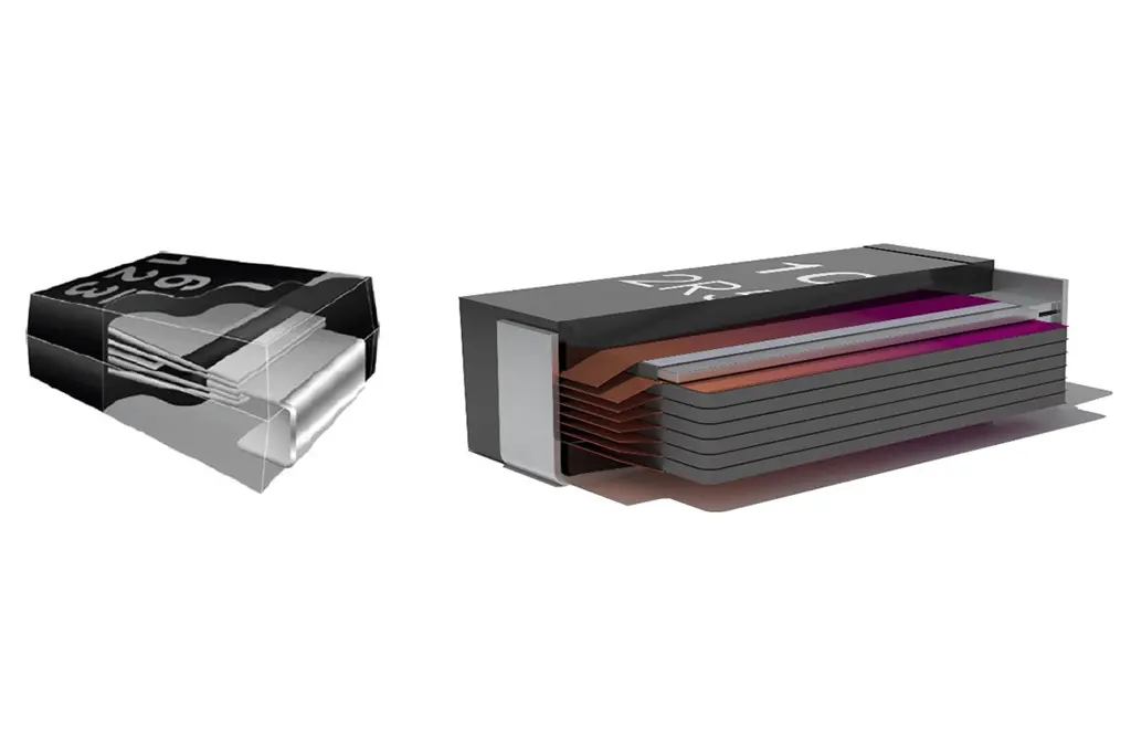
If you keep up with electronic components, the you’ll know solid electrolytic capacitors are all the rage. In this post, we’ll look at these relatively new V-chip style aluminum polymers and compare them to their predecessor – the traditional wet aluminum electrolytic. The advantages include, but are not limited to, lower ESR, better frequency performance, higher ripple handling capability, and longer lifespan.

First, let’s talk about ESR. In general, low ESR minimizes voltage drop and reduces the amount of heat generated by the capacitor as it tries to compensate the current needs of the load. By replacing the wet electrolyte with a solid conductive polymer, the AO-CAPs can achieve ESR values that are in the mΩ range. This is a significant improvement over traditional electrolytic capacitor, whose ESR will be in the Ω range.

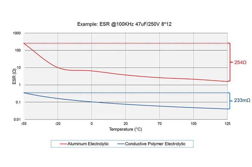
Look at the plot below to see a visual comparison. Not only is the ESR significantly lower for the aluminum polymer, but the temperature stability is leaps and bounds better. You will notice the ESR variance based on temperature with a larger delta for the traditional electrolytic (254 Ω), while the polymer is just a small fraction (233 mΩ).

Next, let’s talk about power. Using Joule’s Law in conjunction with Ohm’s Law, we can calculate power to be P = I2R, where I = RMS Current and R = ESR. Note given the same current, the impact to the heating of the component is defined by the ESR value, which in turn limits is ripple current capability.

Because polymers have significantly less ESR, the ripple current handling capability is improved. Notice that in most cases, the allowable ripple current is several times greater than an equivalent traditional electrolytic.

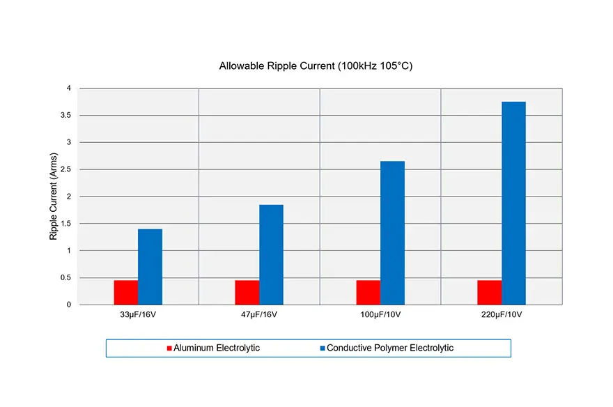
Impedance is also important – especially for decoupling applications. Here, you can see the delta in impedance between traditional electrolytic and polymer. Polymers have about an order of a magnitude less impedance!

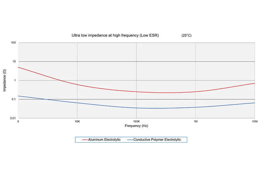
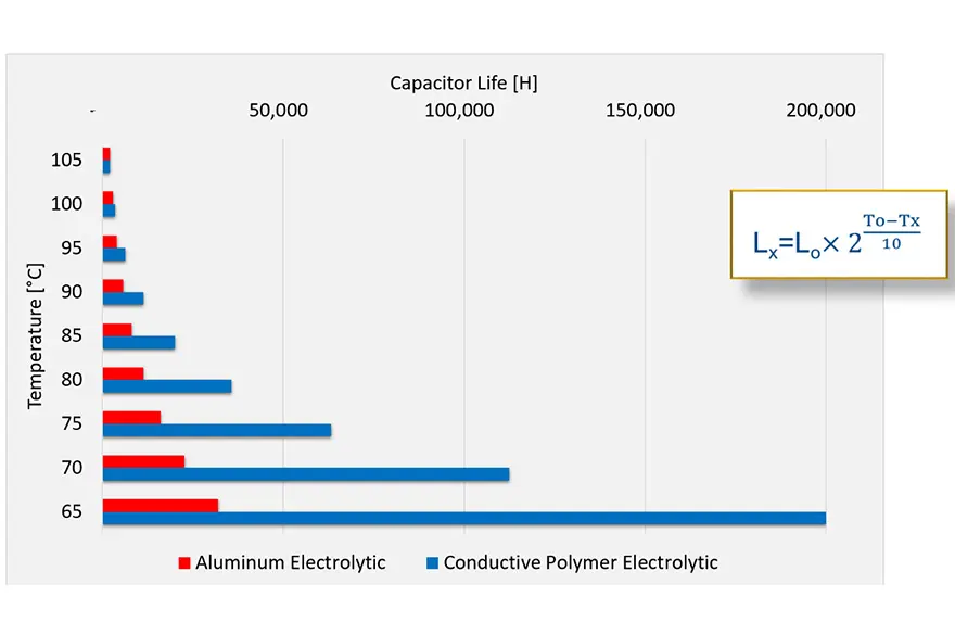
Finally, let’s talk about life. Reference the graph below showing temperature versus life. The polymer starts to show its large increase in life at lower application temperatures. The improvement in life is staggering. This is due to the solid electrolytic system that the polymer has. The main wear-out mechanism in traditional electrolytic caps is the dry-out of the electrolyte. The polymer lacks this wear-out mechanism, and the life is only constrained by the oxidation of the polymer.

Some good rules of thumb you can use to estimate the life of a capacitor:

  • Traditional electrolytic: for every 10°C decrease in temperature, capacitor life increases by 2x.
  • Aluminum polymer: for every 20°C decrease in temperature, capacitor life increases by 10x.


Related

Recent Posts

Non-Linear MLCC Class II Capacitor Measurements Challenges

19.8.2025
19

Researchers Demonstrated HfO Anti-Ferroelectric Flexible Capacitors

19.8.2025
11

Common Mistakes in Flyback Transformer Specs

15.8.2025
30

High Voltage MLCCs Meeting the Growing Demand for Efficiency in Power Conversion

12.8.2025
133

KYOCERA AVX Releases Hermaphroditic WTW and WTB Connectors

8.8.2025
15

Radiation Tolerance of Tantalum and Ceramic Capacitors

8.8.2025
77

TDK Releases Compact Polypropylene Film Capacitors for Resonant Topologies

7.8.2025
34

Percolation Phenomenon and Reliability of Molded Power Inductors in DC/DC converters

6.8.2025
43

Root Causes and Effects of DC Bias and AC in Ceramic Capacitors

6.8.2025
57

Knowles Unveils High-Performance Safety-Certified MLCC Capacitors

6.8.2025
43

Upcoming Events

Aug 27
17:00 - 18:00 CEST

Capacitor Assemblies for High-Power Circuit Designs

Sep 3
15:30 - 17:30 CEST

How to Choose Your Magnetic Supplier

Sep 16
17:00 - 18:00 CEST

EMI Shielding Challenges

Sep 22
September 22 @ 13:00 - September 25 @ 15:15 EDT

Pre Cap Visual Inspection per Mil-Std-883 (TM 2017)

Sep 30
September 30 @ 12:00 - October 2 @ 14:00 EDT

MIL-Std-883 TM 2010

View Calendar

Popular Posts

  • Buck Converter Design and Calculation

    0 shares
    Share 0 Tweet 0
  • Boost Converter Design and Calculation

    0 shares
    Share 0 Tweet 0
  • Flyback Converter Design and Calculation

    0 shares
    Share 0 Tweet 0
  • LLC Resonant Converter Design and Calculation

    0 shares
    Share 0 Tweet 0
  • What is a Dielectric Constant and DF of Plastic Materials?

    4 shares
    Share 4 Tweet 0
  • Ripple Current and its Effects on the Performance of Capacitors

    3 shares
    Share 3 Tweet 0
  • Dual Active Bridge (DAB) Topology Explained

    0 shares
    Share 0 Tweet 0
  • How to Design an Inductor

    0 shares
    Share 0 Tweet 0
  • Core Materials, Permeability and Their Losses

    0 shares
    Share 0 Tweet 0
  • MLCC Case Sizes Standards Explained

    0 shares
    Share 0 Tweet 0

Newsletter Subscription


Passive Components Blog

© EPCI - Leading Passive Components Educational and Information Site

  • Home
  • Privacy Policy
  • EPCI Membership & Advertisement
  • About

No Result
View All Result
  • Home
  • Knowledge Blog
  • Premium Suppliers

© EPCI - Leading Passive Components Educational and Information Site

This website uses cookies. By continuing to use this website you are giving consent to cookies being used. Visit our Privacy and Cookie Policy.
Go to mobile version