Passive Components Blog
No Result
View All Result
  • Home
  • NewsFilter
    • All
    • Aerospace & Defence
    • Antenna
    • Applications
    • Automotive
    • Capacitors
    • Circuit Protection Devices
    • electro-mechanical news
    • Filters
    • Fuses
    • Inductors
    • Industrial
    • Integrated Passives
    • inter-connect news
    • Market & Supply Chain
    • Market Insights
    • Medical
    • Modelling and Simulation
    • New Materials & Supply
    • New Technologies
    • Non-linear Passives
    • Oscillators
    • Passive Sensors News
    • Resistors
    • RF & Microwave
    • Telecommunication
    • Weekly Digest

    Transformer Design Optimization for Power Electronics Applications

    Microhardness — the Hidden Key to Understanding MnOx Cathode Quality in Tantalum Capacitors

    Samsung to Invest in its Philippine MLCC Facility to Meet Automotive Demand

    Lightweight Model for MLCC Appearance Defect Detection

    DMASS Reports First Positive Signs of European Distribution Market in Q3/25

    TAIYO YUDEN Releases 22uF MLCC in 0402 Size for AI Servers

    Wk 44 Electronics Supply Chain Digest

    Bourns Releases High Current Metal Alloy-based, Multilayer Power Chip Inductors

    Smiths Interconnect Extends Space-Qualified, High-Reliability Fixed Chip Attenuators 

    Trending Tags

    • Ripple Current
    • RF
    • Leakage Current
    • Tantalum vs Ceramic
    • Snubber
    • Low ESR
    • Feedthrough
    • Derating
    • Dielectric Constant
    • New Products
    • Market Reports
  • VideoFilter
    • All
    • Antenna videos
    • Capacitor videos
    • Circuit Protection Video
    • Filter videos
    • Fuse videos
    • Inductor videos
    • Inter-Connect Video
    • Non-linear passives videos
    • Oscillator videos
    • Passive sensors videos
    • Resistor videos

    Transformer Design Optimization for Power Electronics Applications

    Common Mode Chokes Selection for RF Circuits in Next-Generation Communication Systems

    Capacitor Self-balancing in a Flying-Capacitor Buck Converter

    How to Select Ferrite Bead for Filtering in Buck Boost Converter

    Power Inductors Future: Minimal Losses and Compact Designs

    Percolation Phenomenon: Degradation of Molded Power Inductors in DC/DC Converters

    Connector PCB Design Challenges

    Efficient Power Converters: Duty Cycle vs Conduction Losses

    Ripple Steering in Coupled Inductors: SEPIC Case

    Trending Tags

    • Capacitors explained
    • Inductors explained
    • Resistors explained
    • Filters explained
    • Application Video Guidelines
    • EMC
    • New Products
    • Ripple Current
    • Simulation
    • Tantalum vs Ceramic
  • Knowledge Blog
  • Suppliers
    • Who is Who
  • PCNS
    • PCNS 2025
    • PCNS 2023
    • PCNS 2021
    • PCNS 2019
    • PCNS 2017
  • Events
No Result
View All Result
Passive Components Blog
No Result
View All Result

LAN Network

20.9.2021
Reading Time: 5 mins read
A A

Basic Principles
In an Ethernet network, all systems are connected to a single transmission line. There are some physical layouts, depending on the cable chosen and on the size of the whole LAN.

Fig. 2.154: Examples of existing network architectures

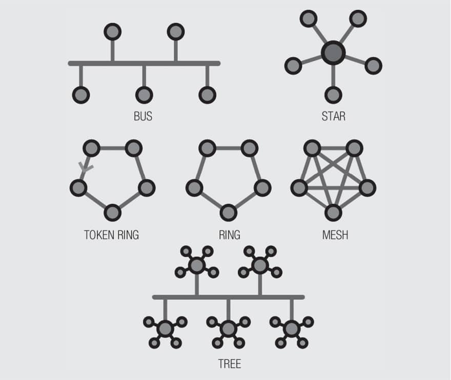
Today, token ring and ring are not so popular anymore and the mesh is certainly the most often used network configuration.

RelatedPosts

Polymer Materials and Processing

What is RF Connector

Connector Materials and Processes

Protocols: 100BaseT & 1000BaseT
Communication in this network is achieved with the help of a protocol. IEEE provides different standards called 802.3xx protocols (xx depending on the speed). Nowadays, the most popular ones are Fast Ethernet (100BaseT) and Gigabit Ethernet (1000BaseT). For such speeds, a LAN network is built with a cat5 (or higher) cable with 4 pairs (Shielded or not). 100BaseT uses only 2 pairs while 1000BaseT needs 4 pairs.

The 8P8C modular Jack (improperly called RJ45) is the first element of the Circuit Board Physical layer often named MDI (Medium Dependent Interface). This physical layer is controlled by an active device called the PHY. Further descriptions about the physical layer you can find in the design guide Trilogy of Magnetics.

Figure 2.155 shows the basic diagram of a physical layer for the 100BaseT.

Fig. 2.155: 100BaseT Basic diagram of the physical layer

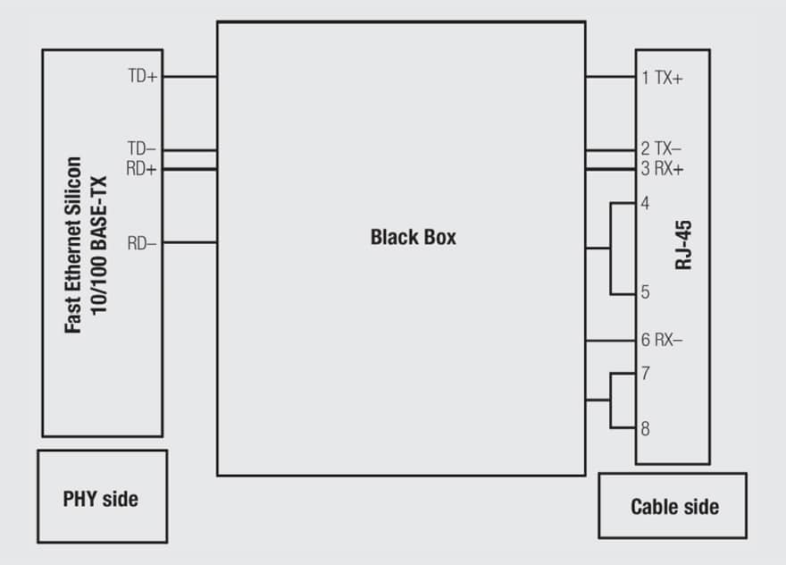
As we can see on Figure 2.155, the pin assignment is pair 1-2 for TX and 3-6 for RX. Pairs 4-5 and 7-8 are not used for 100BaseT (but they are used for Gigabit).

The black box will be detailed later on.

Manufacturers of PHY (according to the Ethernet standard) enable visual control via mechanical means like LED or light pipes, giving the following information: Connection established, Tx, Rx, collisions, speed …

This option is useful within an ‘office’ type application in order to quickly check the online/offline status; it is even more useful with on-board applications. Therefore, it is not surprising to find modular jacks with several LED options.

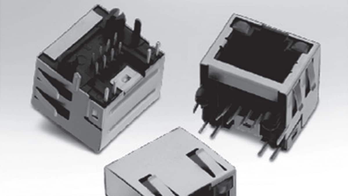
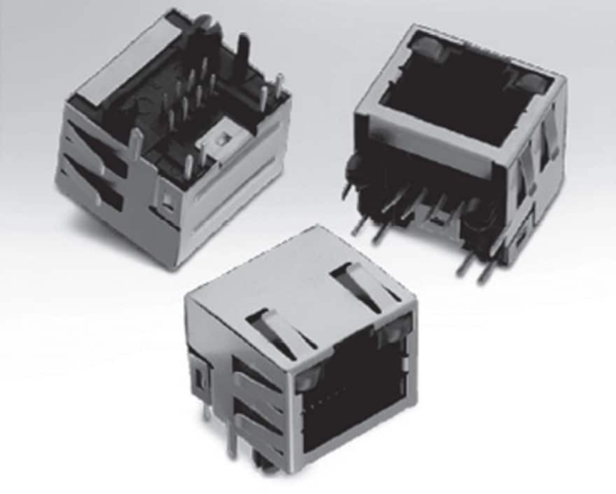
A wide range of products is offered to designers to help them select the right Modular Jack for their applications.

This range consists in a single or multi-port (stacked or not), with tab up or down, shielded or unshielded, EMI fingers and with or without LED.

Single versions are also available in horizontal or vertical positions in SMT or THT PCB board mount.

Fig. 2.156: Example of RJ45, THT shielded with LEDs

What about Insulation?
As explained before, the modular jack is the first element of a physical layer, just between the cable and the electronic board. According to the specifications of the Ethernet standard (802.3), it is necessary to withstand 1500 Vrms 1min between port and chassis ground.

A transformer can easily do the job (it’s the cheapest solution) and help to meet this requirement; the question of having it integrated or not will be discussed later in this chapter.

EMI Reduction: What for?
High speed signal transmission is really sensitive to noise. Noise can easily be generated by the cable and create EMI (Electromagnetic Interferences). On an Ethernet port, noise is often coming in common mode. The best solution to attenuate it without damaging the signal is to use a common mode choke. This is why we always find a transformer and a common mode choke together (the black box described before). This set of components is called a LAN transformer.

Fig. 2.157: 100BaseT physical layer

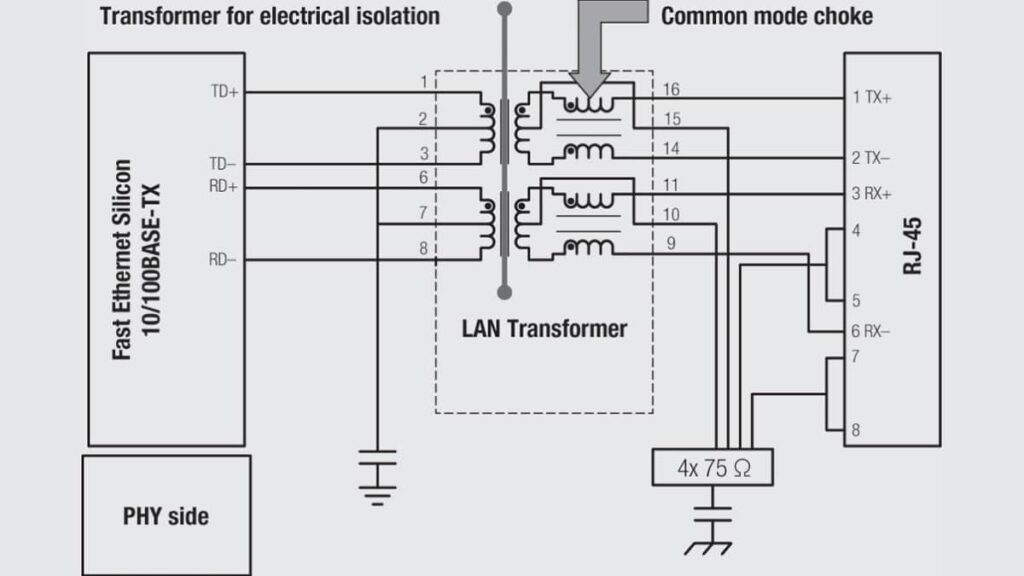
Note: Resistors 4 x 75 Ω together with the capacitor on the bottom right side, form a so called “Bob Smith Termination” used to reduce EMI.

Discrete or Integrated Filtering Solution?
Now is the time to answer the question which arose a bit earlier in this article: “Shall we integrate the LAN Transformer in the connector or should we keep a discrete solution?”

Advantages of integrated solutions are the disadvantages for discrete solutions and vice versa … A designer makes his own decision, he has to balance these parameters against each other.

Advantages of the integrated option
• Lower number of components (lower assembly cost).
• Smaller foot print.

Disadvantages of the integrated option
• Harder to rework if a component fail during test (Higher production cost).
• Smaller size could increase coupling and therefore reduce the common mode effect.

Basically, there is no clear answer to this question, both solutions have advantages and disadvantages. It is not a trivial choice and each application will need to be considered on an individual basis.

Consequences of High Frequency on the Connector Design
The trend for high speed does not only imply changes for filtered connectors but also for the non-filtered ones.

Connector manufacturers created special cat5 connectors with a different pinning, where pin 1/2 and 4/5 have been shifted to compensate potential delays and to make it easier to remain below the maximum 45ns delay skew (see Table 2.14) allowed by EIA.

Basically, any cat5 connector can potentially fit for a cat5e application but the design below makes it easier to comply with the EIA standard.

Fig. 2.158: 615008145521 8P8C Modular Jack with optimised cat5e pinning

It’s even more complex when it comes to higher frequencies like in the cat6 area. In this case we often find connectors with integrated capacitors (mounted on a PCB integrated in the connector) on every line to create a filter that reduces the noise at the entry level of the circuit.

Related

Source: Wurth elektronik

Recent Posts

Connector PCB Design Challenges

3.10.2025
50

Non-Magnetic Interconnects

23.4.2025
27

10 Tips for Ensuring Reliability of Discrete Wire Assemblies

20.2.2025
57

Polymer Materials and Processing

11.8.2025
68

Basic PCB Technology Overview

1.7.2025
26

What is RF Connector

17.12.2024
15

Creepage and Clearance of Connector

25.7.2025
25

Microwave Multi Line Connectors Mounting and Handling Precautions

11.8.2025
3

BASIC PCB Design Rules – Layout

1.7.2025
37

MEMR RF Relay for Space Compact Redundancy Ring

17.12.2024
4

Upcoming Events

Nov 4
November 4 @ 12:00 - November 6 @ 14:15 EST

Wirebond Materials, Processes, Reliability and Testing

Nov 6
14:30 - 16:00 CET

Self-healing polymer materials for the next generation of high-temperature power capacitors

Nov 11
17:00 - 18:00 CET

Industrial Applications Demand More from Interconnects in Next-Gen Designs

View Calendar

Popular Posts

  • Buck Converter Design and Calculation

    0 shares
    Share 0 Tweet 0
  • Boost Converter Design and Calculation

    0 shares
    Share 0 Tweet 0
  • LLC Resonant Converter Design and Calculation

    0 shares
    Share 0 Tweet 0
  • Flyback Converter Design and Calculation

    0 shares
    Share 0 Tweet 0
  • Ripple Current and its Effects on the Performance of Capacitors

    3 shares
    Share 3 Tweet 0
  • MLCC and Ceramic Capacitors

    0 shares
    Share 0 Tweet 0
  • Dual Active Bridge (DAB) Topology

    0 shares
    Share 0 Tweet 0
  • What is a Dielectric Constant and DF of Plastic Materials?

    4 shares
    Share 4 Tweet 0
  • SEPIC Converter Design and Calculation

    0 shares
    Share 0 Tweet 0
  • Flying Capacitors

    0 shares
    Share 0 Tweet 0

Newsletter Subscription


Passive Components Blog

© EPCI - Leading Passive Components Educational and Information Site

  • Home
  • Privacy Policy
  • EPCI Membership & Advertisement
  • About

No Result
View All Result
  • Home
  • Knowledge Blog
  • PCNS

© EPCI - Leading Passive Components Educational and Information Site

This website uses cookies. By continuing to use this website you are giving consent to cookies being used. Visit our Privacy and Cookie Policy.
Go to mobile version