Passive Components Blog
No Result
View All Result
  • Home
  • NewsFilter
    • All
    • Aerospace & Defence
    • Antenna
    • Applications
    • Automotive
    • Capacitors
    • Circuit Protection Devices
    • electro-mechanical news
    • Filters
    • Fuses
    • Inductors
    • Industrial
    • Integrated Passives
    • inter-connect news
    • Market & Supply Chain
    • Market Insights
    • Medical
    • Modelling and Simulation
    • New Materials & Supply
    • New Technologies
    • Non-linear Passives
    • Oscillators
    • Passive Sensors News
    • Resistors
    • RF & Microwave
    • Telecommunication
    • Weekly Digest

    Bourns Unveils Metal Powder Core High Current Low DCR Shielded Power Inductor

    Influence of Tantalum Capacitor Pellets Size on Stability During Oxide Film Formation

    Modelithics Release Discrete Components Optimization Article for RF/Microwave Designers

    Samsung Extends Capacitance of MLCC 0805 X7T 250V to 100nF

    Samtec Releases 800-Position High-Performance Array Connectors  

    DigiKey Announces Back to School Giveaway to Empower Tomorrow’s Innovators

    Ripple Steering in Coupled Inductors: SEPIC Case

    TDK Releases Low Loss Thin-Film Inductors for AI Data Centers

    Samsung Releases Ultra–High-Capacitance 4.7uF 2.5V MLCC in 0201 for AI GPU

    Trending Tags

    • Ripple Current
    • RF
    • Leakage Current
    • Tantalum vs Ceramic
    • Snubber
    • Low ESR
    • Feedthrough
    • Derating
    • Dielectric Constant
    • New Products
    • Market Reports
  • VideoFilter
    • All
    • Antenna videos
    • Capacitor videos
    • Circuit Protection Video
    • Filter videos
    • Fuse videos
    • Inductor videos
    • Inter-Connect Video
    • Non-linear passives videos
    • Oscillator videos
    • Passive sensors videos
    • Resistor videos

    Ripple Steering in Coupled Inductors: SEPIC Case

    SEPIC Converter with Coupled and Uncoupled Inductors

    Coupled Inductors in SEPIC versus Flyback Converters

    Non-Linear MLCC Class II Capacitor Measurements Challenges

    Percolation Phenomenon and Reliability of Molded Power Inductors in DC/DC converters

    Root Causes and Effects of DC Bias and AC in Ceramic Capacitors

    How to Calculate the Output Capacitor for a Switching Power Supply

    Switched Capacitor Converter Explained

    Understanding Inductor Dot Markings and Their Application in LTspice

    Trending Tags

    • Capacitors explained
    • Inductors explained
    • Resistors explained
    • Filters explained
    • Application Video Guidelines
    • EMC
    • New Products
    • Ripple Current
    • Simulation
    • Tantalum vs Ceramic
  • Knowledge Blog
  • Suppliers
    • Who is Who
  • Events
No Result
View All Result
Passive Components Blog
No Result
View All Result

MIL-PRF-32535 QPL SMD BME MLCCs by Kemet explained

9.11.2019
Reading Time: 5 mins read
A A

Source: doEEEt article

Surface mount ceramic capacitors, such as MLCCs, for use in Defense and Aerospace applications usually require a superior level of reliability. To achieve high reliability, capacitor suppliers follow MIL-PRF standards for manufacturing, processing, qualification, and testing and are tightly controlled for design changes and material traceability. Historically, all MLCCs utilized precious metal electrode (PME) technology and is currently the predominate technology in use for high reliability Defense and Aerospace applications.

RelatedPosts

Bourns Unveils Metal Powder Core High Current Low DCR Shielded Power Inductor

Influence of Tantalum Capacitor Pellets Size on Stability During Oxide Film Formation

Modelithics Release Discrete Components Optimization Article for RF/Microwave Designers

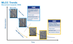
However, when we look at the commercial and automotive trends over the past 30 years, we can see major advancements in technology ranging from PCs, to laptops, cell phones, smart phones, electric vehicles, IoT, autonomous vehicles, and so on. Functionality and circuit density have increased exponentially over time, which means active and passive component size must decrease at the same pace.

In order to shrink the size of MLCCs, while maintaining the same capacitance values, dielectric layers must become as thin as possible. In fact, making MLCC layers thinner is the driving factor for increasing volumetric efficiency. Since MLCCs historically used PME technology, suppliers ran into limitations on how thin the dielectric could be made, while maintaining reliability.

Therefore, Base Metal Electrode (BME) technology was introduced in the early 2000s, which allowed suppliers to create much thinner layers, drastically increase volumetric efficiency, and decrease cost.

Today, BME MLCCs make up the overwhelming majority of MLCCs in used in the electronics industry. These also include many applications where reliability is critical. For example, the automotive industry has been using BME technology for over 15 years in applications such as ABD systems and airbags. The medical industry has been using BME MLCCs in instrumentation and implantable devices for over 10 years.
 

MLCC Trends

BME vs PME

BME vs PME

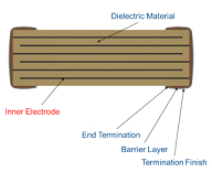
MLCCs are constructed using alternating layers of ceramic dielectric and metal electrodes. BME MLCCs use nickel as the conductive inner electrodes and are the predominant technology for MLCCs today. PME MLCCs use precious metals such as silver or palladium as the inner electrodes. The use of precious metal electrodes increase cost and prevent thinner layers making them poor candidates for high density applications.

The conversion from PME to BME technology in MLCCs helped enable the trend of miniaturization and circuit density for every industry except one, the Defense and Aerospace industry.

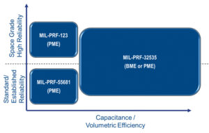
The two predominant specifications for high reliability MLCCs are the MIL-PRF-55681 and MIL-PRF-123.  The MIL-PRF-55681 specification has been around for over 25 years and customers will only use PME MLCCs qualified to this standard. Since this is limited to PME, Defense and Aerospace customers cannot capitalize on miniaturization trends and limits circuit density.

The MIL-PRF-123 specification prevents the use of nickel electrodes (BME MLCCs) and therefore is limited to PME technology, which, as mentioned previously, Defense and Aerospace customers cannot capitalize on mediatization trends and limits design density. This led to the creation of a new standard for high reliability MLCCs, MIL-PRF-32535.
MIL-PRF

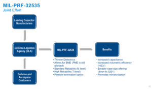
The creation of the MIL-PRF-32535 specification is a joint effort between the Defense Logistics Agency (DLA), leading capacitor manufacturers, and defense/aerospace customers. The new standard allows for thinner dielectrics and the use of BME technology while maintaining the same reliability levels as MIL-PRF-55681 and MIL-PRF-123. In addition, MIL-PRF-32535 is the first standard to allow for a flexible termination to increase flex robustness.

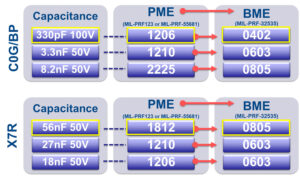
By utilizing BME technology and thinner dielectrics, this specification allows defense and aerospace customers to take advantage of the increase capacitance and smaller case sizes. For example, thanks to the increased volumetric efficiency of BME vs PME, it is possible to replace 18 1206 1nF PME MLCCs with one 1206 18nF BME MLCC.
C0G-BP

Not A Replacement

The MIL-PRF-32535 specification is not intended to replace MIL-PRF-123 or MIL-PRF-55681 but rather allow for thinner dielectric MLCCs and BME technology.

By allowing thinner dielectrics and BME technology, higher capacitance values in the same case size and voltage ratings can now be achieved.  Therefore, the MIL-PRF-32535 specification can be thought of as an extension to the legacy standards that have been in place for many years.
Space grade

KEMET MIL-PRF-32535 are available in M (standard reliability) and T (high reliability) product levels

KEMET was one of the capacitor manufacturers at the forefront of specifying the details behind the MIL-PRF-32535. So much so that KEMET was the first manufacturer to provide capacitors built to the new standard.

The KEMET Hi-Rel BME capacitors are available in a wide range of voltages and case sizes and in both X7R and C0G dielectric platforms.

Related

Recent Posts

Influence of Tantalum Capacitor Pellets Size on Stability During Oxide Film Formation

29.8.2025
10

Modelithics Release Discrete Components Optimization Article for RF/Microwave Designers

28.8.2025
9

Samsung Extends Capacitance of MLCC 0805 X7T 250V to 100nF

28.8.2025
11

Samsung Releases Ultra–High-Capacitance 4.7uF 2.5V MLCC in 0201 for AI GPU

27.8.2025
25

Non-Linear MLCC Class II Capacitor Measurements Challenges

19.8.2025
45

Researchers Demonstrated HfO Anti-Ferroelectric Flexible Capacitors

19.8.2025
19

High Voltage MLCCs Meeting the Growing Demand for Efficiency in Power Conversion

12.8.2025
166

Radiation Tolerance of Tantalum and Ceramic Capacitors

8.8.2025
91

TDK Releases Compact Polypropylene Film Capacitors for Resonant Topologies

7.8.2025
37

Root Causes and Effects of DC Bias and AC in Ceramic Capacitors

6.8.2025
66

Upcoming Events

Sep 3
15:30 - 17:30 CEST

How to Choose Your Magnetic Supplier

Sep 16
17:00 - 18:00 CEST

EMI Shielding Challenges

Sep 22
September 22 @ 13:00 - September 25 @ 15:15 EDT

Pre Cap Visual Inspection per Mil-Std-883 (TM 2017)

Sep 30
September 30 @ 12:00 - October 2 @ 14:00 EDT

MIL-Std-883 TM 2010

Oct 17
12:00 - 14:00 EDT

External Visual Inspection per MIL-STD-883 TM 2009

View Calendar

Popular Posts

  • Buck Converter Design and Calculation

    0 shares
    Share 0 Tweet 0
  • Boost Converter Design and Calculation

    0 shares
    Share 0 Tweet 0
  • Flyback Converter Design and Calculation

    0 shares
    Share 0 Tweet 0
  • LLC Resonant Converter Design and Calculation

    0 shares
    Share 0 Tweet 0
  • What is a Dielectric Constant and DF of Plastic Materials?

    4 shares
    Share 4 Tweet 0
  • Ripple Current and its Effects on the Performance of Capacitors

    3 shares
    Share 3 Tweet 0
  • Dual Active Bridge (DAB) Topology Explained

    0 shares
    Share 0 Tweet 0
  • How to Design an Inductor

    0 shares
    Share 0 Tweet 0
  • Core Materials, Permeability and Their Losses

    0 shares
    Share 0 Tweet 0
  • MLCC Case Sizes Standards Explained

    0 shares
    Share 0 Tweet 0

Newsletter Subscription


Passive Components Blog

© EPCI - Leading Passive Components Educational and Information Site

  • Home
  • Privacy Policy
  • EPCI Membership & Advertisement
  • About

No Result
View All Result
  • Home
  • Knowledge Blog
  • Premium Suppliers

© EPCI - Leading Passive Components Educational and Information Site

This website uses cookies. By continuing to use this website you are giving consent to cookies being used. Visit our Privacy and Cookie Policy.
Go to mobile version