Passive Components Blog
No Result
View All Result
  • Home
  • NewsFilter
    • All
    • Aerospace & Defence
    • Antenna
    • Applications
    • Automotive
    • Capacitors
    • Circuit Protection Devices
    • electro-mechanical news
    • Filters
    • Fuses
    • Inductors
    • Industrial
    • Integrated Passives
    • inter-connect news
    • Market & Supply Chain
    • Market Insights
    • Medical
    • Modelling and Simulation
    • New Materials & Supply
    • New Technologies
    • Non-linear Passives
    • Oscillators
    • Passive Sensors News
    • Resistors
    • RF & Microwave
    • Telecommunication
    • Weekly Digest

    TDK Extends SMT Gate Drive Transformers to 1000 V

    Non-Linear MLCC Class II Capacitor Measurements Challenges

    Researchers Demonstrated HfO Anti-Ferroelectric Flexible Capacitors

    Connector Industry Achieves Double-Digit Growth

    Stackpole Unveils Metal Element High Current Chip Jumpers

    Common Mistakes in Flyback Transformer Specs

    Vishay Releases Miniature SMD Trimmers for Harsh Environments

    Würth Elektronik Releases Push-Button and Main Switches

    Littelfuse Unveils High-Precision TMR Angle Magnetic Sensors

    Trending Tags

    • Ripple Current
    • RF
    • Leakage Current
    • Tantalum vs Ceramic
    • Snubber
    • Low ESR
    • Feedthrough
    • Derating
    • Dielectric Constant
    • New Products
    • Market Reports
  • VideoFilter
    • All
    • Antenna videos
    • Capacitor videos
    • Circuit Protection Video
    • Filter videos
    • Fuse videos
    • Inductor videos
    • Inter-Connect Video
    • Non-linear passives videos
    • Oscillator videos
    • Passive sensors videos
    • Resistor videos

    Non-Linear MLCC Class II Capacitor Measurements Challenges

    Percolation Phenomenon and Reliability of Molded Power Inductors in DC/DC converters

    Root Causes and Effects of DC Bias and AC in Ceramic Capacitors

    How to Calculate the Output Capacitor for a Switching Power Supply

    Switched Capacitor Converter Explained

    Understanding Inductor Dot Markings and Their Application in LTspice

    Accelerating Full Bridge LLC Resonant Converter Design with Frenetic AI

    Understanding Switched Capacitor Converters

    Coupled Inductors Circuit Model and Examples of its Applications

    Trending Tags

    • Capacitors explained
    • Inductors explained
    • Resistors explained
    • Filters explained
    • Application Video Guidelines
    • EMC
    • New Products
    • Ripple Current
    • Simulation
    • Tantalum vs Ceramic
  • Knowledge Blog
  • Suppliers
    • Who is Who
  • Events
No Result
View All Result
Passive Components Blog
No Result
View All Result

Murata develops MLCC with a maximum operating temperature of 200°C that support conductive adhesives

17.2.2016
Reading Time: 2 mins read
A A

source: Murata news

Murata Manufacturing Co., Ltd. has developed the GCB series of monolithic ceramic capacitors (MLCC) which support the conductive adhesives that can be used even in environments with high temperatures exceeding 150°C.

RelatedPosts

TDK Extends SMT Gate Drive Transformers to 1000 V

Non-Linear MLCC Class II Capacitor Measurements Challenges

Researchers Demonstrated HfO Anti-Ferroelectric Flexible Capacitors

These new capacitors are intended for use in products and equipment that are installed in demanding temperature environments such as in the vicinity of the engine compartments of automobiles. Sample shipments have already commenced, and Murata will be gearing up to mass-produce the components at some point during 2016.

Conductive adhesives absorb a stress caused by an expansion and a contraction of a circuit board during temperature changes, and it means that has a higher connection reliability. The automobile market in recent years has been witness to rapid increases in the growing adoption of electronic control for various functions with a view to engineering improvements in safety and environmental performance, and the rate at which electronic products and equipment with this kind of control has been on the rise. Among them are the electronic products and equipment that are incorporated inside engine compartments. As they are exposed to demanding temperature environments, the electronic components used by them must have not only high levels of reliability but a high resistance to heat as well.

As a way of supporting circuit operations in these kinds of high-temperature environments, Murata decided to develop a series of monolithic ceramic capacitors that would have a maximum operating temperature of 200°C and that would be amenable to bonding and mounting using conductive adhesives.

Features
These monolithic ceramic capacitors support the conductive adhesives, now being used in the powertrains and safety devices of automobiles, that satisfy the AEC-Q200 stress test qualifications for passive components. Newly developed electrodes made of nickel (Ni) and palladium (Pd) are employed for the external electrodes of the new capacitors, producing a high bonding reliability with conductive adhesives even during use in high-temperature environments. Furthermore, the terminal electrodes of the capacitors have a superior corrosion resistance compared with our previously available products (GCG series).

Example of structure featured by components that support conductive adhesives

The series consists of a line-up of products with a maximum operating temperature of 200°C. They are ideally suited to the products and devices that are installed in automobiles and work in high-temperature conditions.

Electric characteristics
Operating temperature range: -55°C to 150°C (X8R), -55°C to +200°C (X9M)
Temperature characteristics: X8R, X9M
Rated voltage: 10 to 100 Vdc
Capacitance range: 1000 pF to 0.47 μF

X8R characteristics: A temperature characteristic in which the capacitance change rate is ±15% when the operating temperature range is -55°C to 150°C.
X9M characteristics: A temperature characteristic in which the capacitance change rate is +15/-50% when the operating temperature range is -55°C to 200°C.
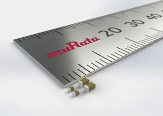
External size
0402 size: 1.0 × 0.5 mm (T=0.5 mm)
0603 size: 1.6 × 0.8 mm (T=0.8 mm)

Production
Mass production scheduled to commence sometime in 2016.

Related

Recent Posts

TDK Extends SMT Gate Drive Transformers to 1000 V

20.8.2025
13

Non-Linear MLCC Class II Capacitor Measurements Challenges

19.8.2025
22

Researchers Demonstrated HfO Anti-Ferroelectric Flexible Capacitors

19.8.2025
13

Stackpole Unveils Metal Element High Current Chip Jumpers

19.8.2025
19

Vishay Releases Miniature SMD Trimmers for Harsh Environments

14.8.2025
13

Littelfuse Unveils High-Precision TMR Angle Magnetic Sensors

13.8.2025
10

Stackpole Extends Voltage of High Temp Chip Resistors

13.8.2025
11

High Voltage MLCCs Meeting the Growing Demand for Efficiency in Power Conversion

12.8.2025
135

Bourns Releases High Power High Ripple Chokes

8.8.2025
35

KYOCERA AVX Releases Hermaphroditic WTW and WTB Connectors

8.8.2025
15

Upcoming Events

Aug 27
17:00 - 18:00 CEST

Capacitor Assemblies for High-Power Circuit Designs

Sep 3
15:30 - 17:30 CEST

How to Choose Your Magnetic Supplier

Sep 16
17:00 - 18:00 CEST

EMI Shielding Challenges

Sep 22
September 22 @ 13:00 - September 25 @ 15:15 EDT

Pre Cap Visual Inspection per Mil-Std-883 (TM 2017)

Sep 30
September 30 @ 12:00 - October 2 @ 14:00 EDT

MIL-Std-883 TM 2010

View Calendar

Popular Posts

  • Buck Converter Design and Calculation

    0 shares
    Share 0 Tweet 0
  • Boost Converter Design and Calculation

    0 shares
    Share 0 Tweet 0
  • Flyback Converter Design and Calculation

    0 shares
    Share 0 Tweet 0
  • LLC Resonant Converter Design and Calculation

    0 shares
    Share 0 Tweet 0
  • What is a Dielectric Constant and DF of Plastic Materials?

    4 shares
    Share 4 Tweet 0
  • Ripple Current and its Effects on the Performance of Capacitors

    3 shares
    Share 3 Tweet 0
  • Dual Active Bridge (DAB) Topology Explained

    0 shares
    Share 0 Tweet 0
  • Core Materials, Permeability and Their Losses

    0 shares
    Share 0 Tweet 0
  • How to Design an Inductor

    0 shares
    Share 0 Tweet 0
  • MLCC Case Sizes Standards Explained

    0 shares
    Share 0 Tweet 0

Newsletter Subscription


Passive Components Blog

© EPCI - Leading Passive Components Educational and Information Site

  • Home
  • Privacy Policy
  • EPCI Membership & Advertisement
  • About

No Result
View All Result
  • Home
  • Knowledge Blog
  • Premium Suppliers

© EPCI - Leading Passive Components Educational and Information Site

This website uses cookies. By continuing to use this website you are giving consent to cookies being used. Visit our Privacy and Cookie Policy.
Go to mobile version