Passive Components Blog
No Result
View All Result
  • Home
  • NewsFilter
    • All
    • Aerospace & Defence
    • Antenna
    • Applications
    • Automotive
    • Capacitors
    • Circuit Protection Devices
    • electro-mechanical news
    • Filters
    • Fuses
    • Inductors
    • Industrial
    • Integrated Passives
    • inter-connect news
    • Market & Supply Chain
    • Market Insights
    • Medical
    • Modelling and Simulation
    • New Materials & Supply
    • New Technologies
    • Non-linear Passives
    • Oscillators
    • Passive Sensors News
    • Resistors
    • RF & Microwave
    • Telecommunication
    • Weekly Digest

    Researchers Enhanced 2D Ferromagnets Performance

    Bourns Releases Two High Current Common Mode Choke Models

    Electronics Weekly Announcing Finalists for Elektra Awards 2025

    Exxelia Exhibit at Electronica India September 17–19, 2025

    Würth Elektronik Announces 2025 Digital WE Days Virtual Conference

    VINATech Unveils Hybrid Energy Storage System to Revolutionize Grid Stability and Power Delivery

    SCHURTER Releases High Performance EV-Fuse

    Panasonic Industry to Double Production of MEGTRON PCB Materials

    5th PCNS Awards Outstanding Passive Component Papers

    Trending Tags

    • Ripple Current
    • RF
    • Leakage Current
    • Tantalum vs Ceramic
    • Snubber
    • Low ESR
    • Feedthrough
    • Derating
    • Dielectric Constant
    • New Products
    • Market Reports
  • VideoFilter
    • All
    • Antenna videos
    • Capacitor videos
    • Circuit Protection Video
    • Filter videos
    • Fuse videos
    • Inductor videos
    • Inter-Connect Video
    • Non-linear passives videos
    • Oscillator videos
    • Passive sensors videos
    • Resistor videos

    Ripple Steering in Coupled Inductors: SEPIC Case

    SEPIC Converter with Coupled and Uncoupled Inductors

    Coupled Inductors in SEPIC versus Flyback Converters

    Non-Linear MLCC Class II Capacitor Measurements Challenges

    Percolation Phenomenon and Reliability of Molded Power Inductors in DC/DC converters

    Root Causes and Effects of DC Bias and AC in Ceramic Capacitors

    How to Calculate the Output Capacitor for a Switching Power Supply

    Switched Capacitor Converter Explained

    Understanding Inductor Dot Markings and Their Application in LTspice

    Trending Tags

    • Capacitors explained
    • Inductors explained
    • Resistors explained
    • Filters explained
    • Application Video Guidelines
    • EMC
    • New Products
    • Ripple Current
    • Simulation
    • Tantalum vs Ceramic
  • Knowledge Blog
  • Suppliers
    • Who is Who
  • Events
No Result
View All Result
Passive Components Blog
No Result
View All Result

Murata introduces Chip inductor for NFC circuits

25.1.2017
Reading Time: 2 mins read
A A

source: Murata news

Murata Manufacturing Co., Ltd. has started production of the LQM18JN Series of chip inductors for near field communication (NFC*1) in January.

RelatedPosts

Researchers Enhanced 2D Ferromagnets Performance

Bourns Releases Two High Current Common Mode Choke Models

Electronics Weekly Announcing Finalists for Elektra Awards 2025

In recent years, an increasing number of electronic devices such as smartphones have included NFC capability. An NFC circuit utilizes a chip inductor for impedance matching*2, however, current with large amplitude flows in an NFC matching circuit. With a common matching inductor, the effect of magnetic saturation*3 hinders the expected performance. The LQM18JN Series has been designed specifically for NFC matching circuits and is not easily impacted by magnetic saturation. In addition, its closed magnetic circuit configuration suppresses interference with surrounding components even at high mounting density, making it ideal for reducing the size of the NFC circuit.

Rating

Part Number Inductance
Q
(or higher)
Self-Resonance
Frequency
(MHz or higher)
Rated Current
(mA)
Nominal Value
(nH)
Tolerance
(%)
LQM18JNR10J00 100 ±5% 8 200 650
LQM18JNR12J00 120 ±5% 8 150 610
LQM18JNR16J00 160 ±5% 8 100 550

Features

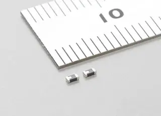
  • Small size at L:1.6×W:0.8×T:0.55mm (Typ.)
  • With ±5% narrow deviation, ideal for matching.

Applications

  • NFC modules mounted in devices such as smartphones.

Part number

LQM18JNxxxx00 (Enter alphanumeric characters at the “x” locations to indicate the inductance and inductance deviation.)
For details see the product page for LQM18JN.

External size


Explanation of Terms
*1. NFC: An acronym for Near Field Communication, in a broader sense it encompasses various standards, but generally it indicates use of the 13.56MHz band at which communication is enabled by touching another NFC compliant device.
*2. Impedance matching: In wireless communication circuits, when components of differing specific impedance for a route in which a signal flows are connected, a reflection of the signal occurs, and this lowers the power of the signal being transferred, and it is therefore linked to a decrease in the sensitivity of the wireless circuit. To counter this, an impedance matching circuit is inserted between components of differing specific impedance so that reflection does not occur, and the related operation is called impedance matching.
*3. Magnetic saturation: When a large current flows with an inductor having a strong magnetic body such as ferrite, a phenomenon is generated wherein the inductance drops. This is called magnetic saturation of the inductor. When magnetic saturation of the inductor is generated in a matching circuit, the inductance falls and therefore the inductance required for matching cannot be maintained, and this lowers the precision of the matching.

Related

Recent Posts

Researchers Enhanced 2D Ferromagnets Performance

16.9.2025
2

Bourns Releases Two High Current Common Mode Choke Models

16.9.2025
1

Electronics Weekly Announcing Finalists for Elektra Awards 2025

16.9.2025
3

Exxelia Exhibit at Electronica India September 17–19, 2025

15.9.2025
23

Würth Elektronik Announces 2025 Digital WE Days Virtual Conference

15.9.2025
10

5th PCNS Awards Outstanding Passive Component Papers

14.9.2025
34

Würth Elektronik Unveils Compact Common-Mode Data Lines Chokes

3.9.2025
34

Bourns Releases Automotive High Creepage and Clearance Transformer

1.9.2025
31

Bourns Unveils Metal Powder Core High Current Low DCR Shielded Power Inductor

29.8.2025
38

Modelithics Release Discrete Components Optimization Article for RF/Microwave Designers

28.8.2025
15

Upcoming Events

Sep 22
September 22 @ 13:00 - September 25 @ 15:15 EDT

Pre Cap Visual Inspection per Mil-Std-883 (TM 2017)

Sep 30
September 30 @ 12:00 - October 2 @ 14:00 EDT

MIL-Std-883 TM 2010

Oct 17
12:00 - 14:00 EDT

External Visual Inspection per MIL-STD-883 TM 2009

Oct 20
October 20 - October 23

Digital WE Days 2025 – Virtual Conference

Oct 21
October 21 @ 12:00 - October 23 @ 14:15 EDT

Space and Military Standards for Hybrids and RF Microwave Modules

View Calendar

Popular Posts

  • Buck Converter Design and Calculation

    0 shares
    Share 0 Tweet 0
  • Boost Converter Design and Calculation

    0 shares
    Share 0 Tweet 0
  • Flyback Converter Design and Calculation

    0 shares
    Share 0 Tweet 0
  • LLC Resonant Converter Design and Calculation

    0 shares
    Share 0 Tweet 0
  • Dual Active Bridge (DAB) Topology Explained

    0 shares
    Share 0 Tweet 0
  • Ripple Current and its Effects on the Performance of Capacitors

    3 shares
    Share 3 Tweet 0
  • What is a Dielectric Constant and DF of Plastic Materials?

    4 shares
    Share 4 Tweet 0
  • SEPIC Converter Design and Calculation

    0 shares
    Share 0 Tweet 0
  • How to Design an Inductor

    0 shares
    Share 0 Tweet 0
  • Core Materials, Permeability and Their Losses

    0 shares
    Share 0 Tweet 0

Newsletter Subscription


Passive Components Blog

© EPCI - Leading Passive Components Educational and Information Site

  • Home
  • Privacy Policy
  • EPCI Membership & Advertisement
  • About

No Result
View All Result
  • Home
  • Knowledge Blog
  • Premium Suppliers

© EPCI - Leading Passive Components Educational and Information Site

This website uses cookies. By continuing to use this website you are giving consent to cookies being used. Visit our Privacy and Cookie Policy.
Go to mobile version