Passive Components Blog
No Result
View All Result
  • Home
  • NewsFilter
    • All
    • Aerospace & Defence
    • Antenna
    • Applications
    • Automotive
    • Capacitors
    • Circuit Protection Devices
    • electro-mechanical news
    • Filters
    • Fuses
    • Inductors
    • Industrial
    • Integrated Passives
    • inter-connect news
    • Market & Supply Chain
    • Market Insights
    • Medical
    • Modelling and Simulation
    • New Materials & Supply
    • New Technologies
    • Non-linear Passives
    • Oscillators
    • Passive Sensors News
    • Resistors
    • RF & Microwave
    • Telecommunication
    • Weekly Digest

    Samsung Electro-Mechanics Releases High-Capacitance MLCCs for AI Server Applications

    Samsung Electro-Mechanics Releases 165C Automotive 0806 Size Power Inductors

    Coupled Inductors Circuit Model and Examples of its Applications

    Würth Elektronik Introduces LTspice Models for ESD Products

    Capacitor Ripple Current Testing: A Design Consideration

    TDK Releases 0201 High-Frequency Smallest Inductors

    Coilcraft Extends Air Core RF Inductors

    Bourns Releases Automotive 1W Flyback Transformer

    Wk 20 Electronics Supply Chain Digest

    Trending Tags

    • Ripple Current
    • RF
    • Leakage Current
    • Tantalum vs Ceramic
    • Snubber
    • Low ESR
    • Feedthrough
    • Derating
    • Dielectric Constant
    • New Products
    • Market Reports
  • VideoFilter
    • All
    • Antenna videos
    • Capacitor videos
    • Circuit Protection Video
    • Filter videos
    • Fuse videos
    • Inductor videos
    • Inter-Connect Video
    • Non-linear passives videos
    • Oscillator videos
    • Passive sensors videos
    • Resistor videos

    Coupled Inductors Circuit Model and Examples of its Applications

    Inductor Resonances and its Impact to EMI

    Highly Reliable Flex Rigid PCBs, Würth Elektronik Webinar

    Causes of Oscillations in Flyback Converters

    How to design a 60W Flyback Transformer

    Modeling and Simulation of Leakage Inductance

    Power Inductor Considerations for AI High Power Computing – Vishay Video

    Coupled Inductors in Multiphase Boost Converters

    VPG Demonstrates Precision Resistor in Cryogenic Conditions

    Trending Tags

    • Capacitors explained
    • Inductors explained
    • Resistors explained
    • Filters explained
    • Application Video Guidelines
    • EMC
    • New Products
    • Ripple Current
    • Simulation
    • Tantalum vs Ceramic
  • Knowledge Blog
  • Suppliers
    • Who is Who
  • Events
No Result
View All Result
Passive Components Blog
No Result
View All Result

Ohm’s Law Answers Your Questions

21.1.2022
Reading Time: 6 mins read
A A

Understanding these concepts will help you solve more than theoretical problems. Understanding electronics, electronic components, resistors and electronic troubleshooting starts with knowing Ohm’s Law. This is not difficult and can make your work so much easier.

Ohm’s Law was a constant companion over my long career as a radio broadcast engineer. The relationships among volts, amperes, ohms and power made it all so understandable.

RelatedPosts

Samsung Electro-Mechanics Releases High-Capacitance MLCCs for AI Server Applications

Samsung Electro-Mechanics Releases 165C Automotive 0806 Size Power Inductors

Coupled Inductors Circuit Model and Examples of its Applications

German physicist Georg Ohm published the concept in 1827, almost 200 years ago. It was later recognized as Ohm’s Law and has been described as the most important early quantitative description of the physics of electricity.

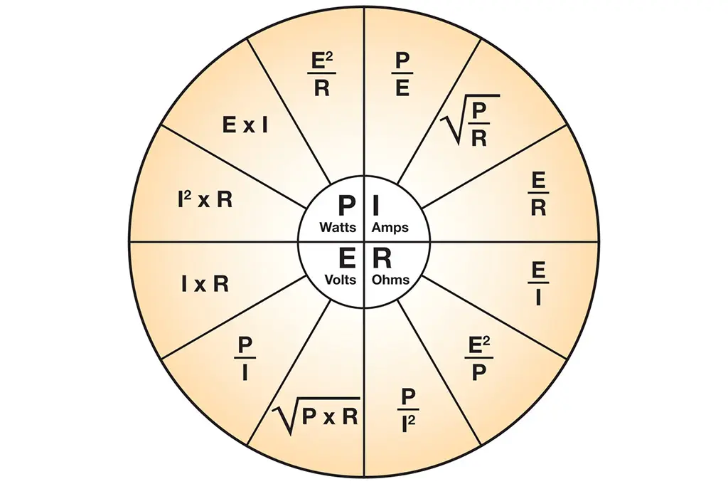
Featured image Fig. 1 above is a list of simple formulas for using Ohm’s Law. Nothing complicated, just good answers to your questions. You don’t need to be a mathematician to run the calculations. The calculator on your smartphone will handle this easily.

P is for power in watts, I is current in amperes, R is resistance in ohms and E is voltage in volts. Solve for any of those knowing two of the other parameters.

OHM’S LAW ON CURRENT

When I look at a 100 watt light bulb, I think 120 volts at about 0.8 amperes (0.8333 amperes is more exact). That is 100 watts of power being consumed.

So how many lights can be put on a 15 ampere circuit breaker? Let’s see — 15 ampere circuit capacity, divided by 0.8333 amperes for each bulb in parallel = 18 lamps. Conversely, it is 18 lamps X 0.8333 amperes per lamp = 14.9994 amperes … right at the limit of the circuit breaker.

The rule here says you don’t put more than an 80-percent load on any circuit breaker for fuse, which is 14 lamps in this case. Always keep some headroom in a circuit. As you know, breakers and fuses are used to protect against fires or other dramatic failures during circuit problems. They get unreliable at their current limit. You don’t need nuisance break trips or fuse burn-outs from running too close to the line.

OHM’S LAW

There are not many high-level plate modulated AM transmitters around anymore. The Gates BC-1 series is an example of this 1950 to 1970s technology. The design typically has 2600 volts running the RF Power Amplifier tubes.

Power supplies like that need a “bleeder” resistor between the high voltage and ground to bring down/bleed the high voltage to zero when the transmitter is turned off. This should happen in only a second or so of time. The power supply could stay hot with high voltage for minutes or hours if the bleeder resistor fails open. That is a serious safety issue for the engineer working on it, if he or she fails to short the high voltage filter capacitor before touching any part of the transmitter.

Ohm’s Law tells us that 2600 volts across the resistor squared (times itself) then divided by 100,000 ohms resistance equals 67.6 watts of power dissipation required on a continuous basis on a 100 watt resistor. You would think that the 32.4-percent safety margin would be enough. This resistor typically failed after 10 years of use. The answer is in the ventilation the resistor gets for cooling. The 67.6 watts in heat has to go somewhere. This transmitter model has some, but not a lot, of air flow on the bottom where the resistor is located.

My answer was to replace the 100 watt resistor with a resistor rated at 225 watts, as seen in the center of the photo. It gave more surface area so it ran cooler, thus longer. A 100 watt resistor is $15.14 vs $18.64 for a 225 watt unit. It is only a $3.50 difference for a huge increase in reliability and safety. The screw that holds it in place will need to be longer if you do this modification. No big deal.

Yes, there is a meter multiplier resistor string next to the resistor and high-voltage capacitor. It samples the high voltage for the PA voltmeter. Dirt has accumulated on the high-voltage end of the string. It is high voltage that attracts dirt, requiring frequent cleaning to maintain transmitter reliability. It’s maintenance.

The RF dummy load in this transmitter has six 312 ohm/200 watt non-inductive resistors. The transmitter sees the 52 ohms because the resistors are in parallel. Simple math, 312 ohms divided by 6 resistors = 52 ohms. Yes, 52 ohms, 51.5 ohms, 70 ohms and other impedances were common in the past before solid-state transmitters more or less forced the standard to be 50 ohms. Tube-based transmitters will tune into almost any load while solid-state transmitters are designed to perform into 50 ohm loads….and don’t give me no VSWR!

OHM’S LAW ON VOLTAGE

Let’s say we know that 2 amperes of current is going into a 100 ohm resistor. What is the voltage across the resistor?

The formula is 2 amperes x 100 ohms resistance = 200 volts. From that, we can solve for power in the resistor. It is 200 volts x 2 amperes current = 400 watts.

OHM’S LAW ON POWER

A Continental 816R-2 FM 20 KW FM transmitter might have 7000 volts on the plate of the PA tube with 3.3 amperes of current drawn. Ohm’s Law tell us that 7000 volts x 3.3 amperes = 23,100 watts of power. That is transmitter power input, not output. The power output is subject to the power amplifier efficiency, which is typically 75%. Then, the transmitter power output is 17,325 watts. That also means that 25% of the input power is lost in heat. That is 23,100 watts of input power x .25 = 5775 watts of heat.

Be sure to check the manufacturer’s data sheets for exact numbers for each transmitter model.

HALF POWER?

Half power doesn’t mean the transmitter’s PA voltage is half. If it was half, then the PA current would be half and RF output would be one-quarter. You’ll remember when local Class 4 (now Class C) AM stations ran 1000 watts day and 250 watts at night.

A Gates BC-1 transmitter might have 2600 PA volts and 0.51 amperes of PA current during the day. We can determine the resistance of the power amplifier by taking the PA voltage of 2600 and dividing it by PA current of 0.51 amperes. The answer is 5098 ohms.

That same PA resistance applies regardless of the power level of this transmitter. At quarter power, the PA voltage is 1300 volts. Ohm’s law, using the same 5098 ohms, tells us that the PA current should be 0.255 amperes. Yes, it worked out that way in practice. The simple trick was to connect 120 VAC to the primary of the transmitter’s high voltage transformer for night operation in place of 240 VAC in the day.

With quarter power, the antenna ammeter read half and the signal field intensity was half, not one-quarter. Let’s examine this. If you have a 50 ohm antenna and 1000 watts of power, what is the antenna current? Using Ohm’s Law, take 1000 watts divided by 50 ohms = 20. The square root of that is 4.47 amperes. Divide 250 watts by the same 50 ohm antenna resistance and you get 5. The square root of that is 2.236 amperes, half of the day antenna current. It’s Ohm’s Law.

Think Ohm’s Law when you are on the job. It answers your questions and makes perfect sense.

About author: Mark Persons, WØMH, is an SBE Certified Professional Broadcast Engineer; he was named the Robert W. Flanders SBE Engineer of the Year for 2018. Mark is now retired after more than 40 years in business.

Related

Source: RadioWorld

Recent Posts

Coupled Inductors Circuit Model and Examples of its Applications

21.5.2025
21

Würth Elektronik Introduces LTspice Models for ESD Products

21.5.2025
25

Littelfuse Gate Driver Integrates Diode and Current Limit Resistor in Compact IC

21.5.2025
7

Capacitor Ripple Current Testing: A Design Consideration

21.5.2025
33

Inductor Resonances and its Impact to EMI

16.5.2025
48

Causes of Oscillations in Flyback Converters

15.5.2025
26

Vishay Releases Automotive SMD Thick Film Power Resistor for Enhanced Protection Against Short Transient Pulses

14.5.2025
11

How to design a 60W Flyback Transformer

12.5.2025
42

Bourns Extends Rotational Life Option for its Guitar Potentiometer

9.5.2025
8

Modeling and Simulation of Leakage Inductance

9.5.2025
36

Upcoming Events

May 28
16:00 - 17:00 CEST

Power Over Data Line

View Calendar

Popular Posts

  • Buck Converter Design and Calculation

    0 shares
    Share 0 Tweet 0
  • Boost Converter Design and Calculation

    0 shares
    Share 0 Tweet 0
  • Flyback Converter Design and Calculation

    0 shares
    Share 0 Tweet 0
  • LLC Resonant Converter Design and Calculation

    0 shares
    Share 0 Tweet 0
  • Flying Capacitors Explained

    0 shares
    Share 0 Tweet 0
  • How to Design an Inductor

    0 shares
    Share 0 Tweet 0
  • Dual Active Bridge (DAB) Topology Explained

    0 shares
    Share 0 Tweet 0
  • Ripple Current and its Effects on the Performance of Capacitors

    3 shares
    Share 3 Tweet 0
  • Capacitor Ripple Current Testing: A Design Consideration

    0 shares
    Share 0 Tweet 0
  • Capacitor Losses (ESR, IMP, DF, Q), Series or Parallel Eq. Circuit ?

    0 shares
    Share 0 Tweet 0

Newsletter Subscription


Passive Components Blog

© EPCI - Leading Passive Components Educational and Information Site

  • Home
  • Privacy Policy
  • EPCI Membership & Advertisement
  • About

No Result
View All Result
  • Home
  • Knowledge Blog
  • Premium Suppliers

© EPCI - Leading Passive Components Educational and Information Site

This website uses cookies. By continuing to use this website you are giving consent to cookies being used. Visit our Privacy and Cookie Policy.
Go to mobile version