


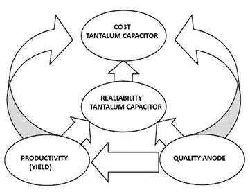
This article written by Dr. Vladimir Azbel, independent consultant on tantalum capacitors, provides an overview of the method used to calculate and develop an anode for a new tantalum capacitor design. It also proposes a program that significantly enhances the anode development process, making it more efficient, reliable, and cost-effective.
This program aids developers in optimizing production parameters, minimizing risks of overheating and defects, and improving the overall reliability and stability of the leakage current (DCL) in finished capacitors.
Introduction
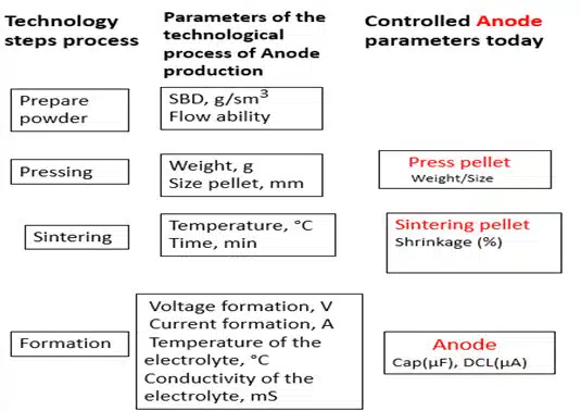
The development of a new design of a tantalum capacitor begins with the construction of the anode recipe, with the choice of its main parameters: the dimensions of the pressed pellet, setting its mass (pressing density), sintering temperature/time, capacitance, formation voltage, powder, as well as the conductivity, temperature of the electrolyte and the electrolysis current.
The choice of calculated values of the parameters for constructing the anode recipe is taken as the basis of the experiment design matrix, in which the numerical values of the parameters and their variations are often the subjective choice of the developer and do not allow for predicting the risk of failures by DCL.
Obtaining an acceptable anode, with the possibility of predicting the DCL, is associated with optimizing all its parameters, which leads to an increase in the number of variable parameter values in the design experiment, and, accordingly, to an increase in financial and time expenses.
Existing Anode Calculation Methods
- Determining the Volume of the Anode The volume of the anode is determined by its geometric dimensions.
- Capacitance (C) and Rating Voltage (RV) The RV and C of the capacitor are set as the main parameters of the device.
- Formation Voltage (FV) The FV is chosen as the RV multiplied by a factor (usually from 2 to 4). The factor depends on the reliability requirements of the capacitor.
- Determining the Specific Capacitance (CV/g) of the Anode The CV/g of the anode is determined by the product of the C and the FV divided by the mass of the anode using the formula:
- Specific Capacitance = C⋅FV/m, where:
- C is the capacitance
- FV is the electrolysis voltage
- m is the mass of the anode
- Specific Capacitance = C⋅FV/m, where:
- Choice of powder to the required capacitor design. Relationship between powder CV/g values and FV of tantalum capacitors.
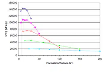
Each type of tantalum powder corresponds to a certain average primary particle diameter and accordingly BET and CV/g. If in the expression CV/g instead of C take the value of the required capacity (C1), and instead of V – the value FV, and permissible mass of the anode, which depends on the pressing density of the pellet, set by the manufacturer capacitor, then the value C1*FV/g corresponds to the value CV/g of powder which can be used to obtain the required capacitor design.
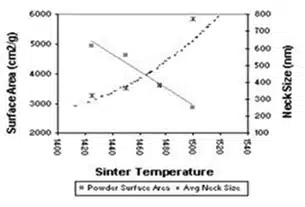
The size of the powder particles directly affects the powder surface area (see Fig. 4), and the following expression describes the relationship between them: SSA = 6/d*ρ, where d is the average size of the primary powder particle, ρ is the skeletal porosity of the sample.
The relationship between BET/SSA and CV/g for tantalum powders is shown in Fig. 4.
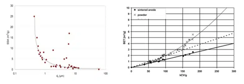
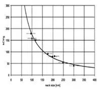
Fig. 5 (right) Dependency of the surface area of the sintered anode on specific capacitance (HC Starck).
Advantage of the Program
- Leakage Current (DCL) Failure Risk Prediction: The program predicts the risk of failures due to leakage current, enhancing the reliability of capacitors. This is particularly crucial for applications in critical systems where failures are unacceptable.
- Overheating Risk Prediction, at Formation: The program forecasts the risk of overheating during anode production, reducing the likelihood of defects and increasing the reliability of the finished capacitor.
- Parameter Optimization: The program optimizes anode parameters such as dimensions, mass, pressing density, sintering temperature/time, capacitance, forming voltage, powder type, electrolyte conductivity and temperature, and electrolysis current. The indicator’s, positive influence on changes in the mentioned parameters, is an increased Δ value. This ensures the production of the most efficient and reliable anodes.
- Thermal Balance Optimization: The program assists developers in selecting technological parameters that ensure optimal thermal balance in the anode neck area, preventing overheating and associated defects.
- Comprehensive Parameter Approach: The program considers the interrelationship between various technological parameters and their impact on anode structure and heat exchange processes. Changing one parameter to improve a specific characteristic does not degrade other parameters.
- Minimization of Residual Stresses and Defects: The program minimizes the risk of residual stresses and defects arising from overheating, enhancing the durability and stability of the leakage current (DCL) during the capacitor’s operation.
- Heat Transfer Modeling: The program models heat transfer processes in critical zones of the anode, such as the necks between particles, allowing more accurate prediction of parameters necessary for stable capacitor operation.
- Reduction of Financial and Time Costs: The program reduces the need for extensive experimental research by offering optimal modeling parameters, thus lowering development and time costs.
- Flexibility and Adaptation: The program allows developers who do not have experience in calculating new capacitor designs to increase the efficiency of the development process and reduce the number of experimental runs.
- Utilization of Existing Data: The program uses parameter values anode, received method striping, from commercially available capacitors, to establish optimality criteria (Δ value). This allows you to rely on verified data and increases the accuracy of calculations.
- Impregnation Risk Assessment (ϕ): The program also assesses impregnation risk, which improves production processes.
Example of Program Operation
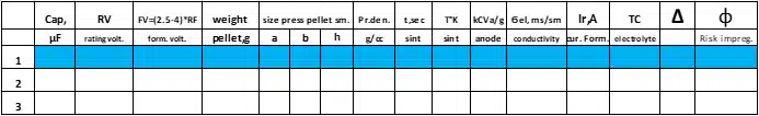
- Parameter Input: The initial parameter values are entered into the program: pressing pellet – dimensions, weight; anode – capacity, rating voltage; formation – conductivity of the electrolyte, its temperature, and formation current.
Figures 7 and 8 illustrate the relationship between surface area, inter-particle sinter neck size, and capacitance for different tantalum powders.
- Heat Transfer Modeling: The program models heat transfer processes in the anode neck area, evaluating the impact of parameter changes on thermal balance.
- Δ Coefficient Calculation: The program calculates the Δ coefficient, which indicates thermal balance. The higher the Δ value, the lower the risk of overheating.
- Parameter Variation: The program varies the parameters and calculates the Δ value for each set of values.
- Optimal Values Determination: The program selects the parameter values corresponding to the maximum Δ value.
- Cathode Impregnation Risk Assessment: The program also assesses cathode impregnation risk, helping to improve production processes and reduce the likelihood of defects.
Conclusion
The proposed program significantly enhances the anode development process for tantalum capacitors, making it more efficient, reliable, and cost-effective. It provides developers with a powerful tool for optimizing production parameters, minimizing overheating and defect risks, and improving the overall reliability and stability of the leakage current (DCL) in finished capacitors.
Appendix: Key Parameters Used in the Program
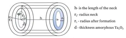
CV/g of the powder depends not only on the particle size of the powder but also on the temperature of its sintering, see Fig. 9. Model of sintering of two particles, see Fig. 10.
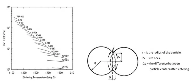
Fig. 10. (right) Geometric model of sintering of two particles
Data from Cabot Supermetals and Sanford Advance Materials were used to obtain information about the relationship between the primary particle size of tantalum powder, its CV/g, and recommended sintering temperatures.
Data on the effect of pressing density, sintering temperature, and formation voltage on the change in pore size and their SSA for powders of different CV/g are presented in detail in the works of H.C. Stark.
To evaluate the criterion of the value of Δ corresponding to an acceptable anode, the program included values of technological parameters of anodes and capacitors that have passed reliability tests and are commercially available. This made it possible to set the value of Δ corresponding to the acceptable values of the anode parameters and test the program.
To evaluate the criterion of the value of Δ corresponding to an acceptable anode, the program included values of technological parameters of anodes and capacitors that have passed reliability tests and are commercially available. This made it possible to set the value of Δ corresponding to the acceptable values of the anode parameters and test the program.
Acknowledgement
I would to express my gratitude to Dr. Tomas Zednicek, from the EPCI European Passive Components Institute, Czech Republic, for his support and valuable recommendations while writing this article.


