Passive Components Blog
No Result
View All Result
  • Home
  • NewsFilter
    • All
    • Aerospace & Defence
    • Antenna
    • Applications
    • Automotive
    • Capacitors
    • Circuit Protection Devices
    • electro-mechanical news
    • Filters
    • Fuses
    • Inductors
    • Industrial
    • Integrated Passives
    • inter-connect news
    • Market & Supply Chain
    • Market Insights
    • Medical
    • Modelling and Simulation
    • New Materials & Supply
    • New Technologies
    • Non-linear Passives
    • Oscillators
    • Passive Sensors News
    • Resistors
    • RF & Microwave
    • Telecommunication
    • Weekly Digest

    Modelithics Library for MATLAB: Measurement-Based Models for Microwave and RF Passive Components

    Bourns Extends Multilayer Chip Inductors Offer for RF and Wireless Designs

    Researchers developed a polymer capacitor by combining two cheap, commercially available plastics. The new polymer capacitor makes use of the transparent material — pictured here, with vintage Penn State athletic marks visible through it — to store four times the energy and withstand significantly more heat.  Credit: Penn State

    Penn State Demonstrated Polymer Alloy Capacitor Film with 4× Energy Density up to 250C

    ECIA January 2026 Reports Strong Sales Confidence

    Vishay Unveils Ultra-Compact 0201 Thick Film Chip Resistors

    Würth Elektronik Component Data Live in Accuris

    Coilcraft Releases Automotive Common Mode Chokes

    MLCC Manufacturers Consider Price Increase as AI Demand Outpaces Supply

    YAGEO Extends Antenna Portfolio with Wi‑Fi 6E/7 and Tri‑band GNSS Solutions

    Trending Tags

    • Ripple Current
    • RF
    • Leakage Current
    • Tantalum vs Ceramic
    • Snubber
    • Low ESR
    • Feedthrough
    • Derating
    • Dielectric Constant
    • New Products
    • Market Reports
  • VideoFilter
    • All
    • Antenna videos
    • Capacitor videos
    • Circuit Protection Video
    • Filter videos
    • Fuse videos
    • Inductor videos
    • Inter-Connect Video
    • Non-linear passives videos
    • Oscillator videos
    • Passive sensors videos
    • Resistor videos

    2026 Power Magnetics Design Trends: Flyback, DAB and Planar

    Enabling Software‑Defined Vehicle Architectures: Automotive Ethernet and Zonal Smart Power

    Calculating Resistance Value of a Flyback RC Snubber 

    One‑Pulse Characterization of Nonlinear Power Inductors

    Thermistor Linearization Challenges

    Coaxial Connectors and How to Connect with PCB

    PCB Manufacturing, Test Methods, Quality and Reliability

    Transformer Behavior – Current Transfer and Hidden Feedback

    Choosing the Right Capacitor: The Importance of Accurate Measurements

    Trending Tags

    • Capacitors explained
    • Inductors explained
    • Resistors explained
    • Filters explained
    • Application Video Guidelines
    • EMC
    • New Products
    • Ripple Current
    • Simulation
    • Tantalum vs Ceramic
  • Knowledge Blog
  • DossiersNew
  • Suppliers
    • Who is Who
  • PCNS
    • PCNS 2025
    • PCNS 2023
    • PCNS 2021
    • PCNS 2019
    • PCNS 2017
  • Events
No Result
View All Result
Passive Components Blog
No Result
View All Result

Researchers Propose Accurate Calculation for Inductor Air Gap in High Power Converters

13.2.2024
Reading Time: 5 mins read
A A

Researchers from College of Electrical Engineering and Automation, Fuzhou University, China presented a novel more accurate calculation method for inductor air gap length in high power DC–DC converters.

Abstract

High-power inductors are fundamental components in high-power DC–DC converters, with their performance being a crucial metric of converter efficiency. This paper presents an in-depth analysis of a novel calculation method for the air gap length in such inductors.

RelatedPosts

Modelithics Library for MATLAB: Measurement-Based Models for Microwave and RF Passive Components

Bourns Extends Multilayer Chip Inductors Offer for RF and Wireless Designs

Penn State Demonstrated Polymer Alloy Capacitor Film with 4× Energy Density up to 250C

Taking into account the effects of air gap diffusion and the winding magnetic field, an expression for the air gap diffusion radius is derived, focusing on a distributed air gap structure. Furthermore, models for calculating the air gap and winding reluctance are developed, grounded in electromagnetic field theory. An equivalent magnetic circuit model, formulated based on Kirchhoff’s second law, facilitates the proposed method for air gap length calculation. This study also involves the development of 3D models for both discrete and decoupled integrated inductors.

The comparison between simulation outcomes and calculated air gap lengths indicates a maximum error of less than 8%, with the minimum error being as low as − 0.79%. Compared with traditional methods, the calculation method proposed in this paper has significant advantages. Additionally, the discrepancy between calculated values and experimental measurements is found to be 1.11%. These results validate the accuracy and applicability of the theoretical analysis and calculation method, underscoring their significance in the design and optimization of high-power DC–DC converters.

Magnetic reluctance analysis and modeling

In high-power DC–DC converters, a significant DC component in inductors makes the magnetic core prone to saturation. Therefore, introducing an air gap becomes necessary to address this issue. For a pre-designed inductor in such a converter, parameters like inductance value, number of turns in the winding, magnetic core cross-sectional area, etc., are predetermined. The air gap length can be calculated by establishing the magnetic reluctance model of the inductor. This paper focuses on the topology of a high-power DC–DC converter, specifically an interleaved parallel Buck-Boost converter.

Winding reluctance analysis

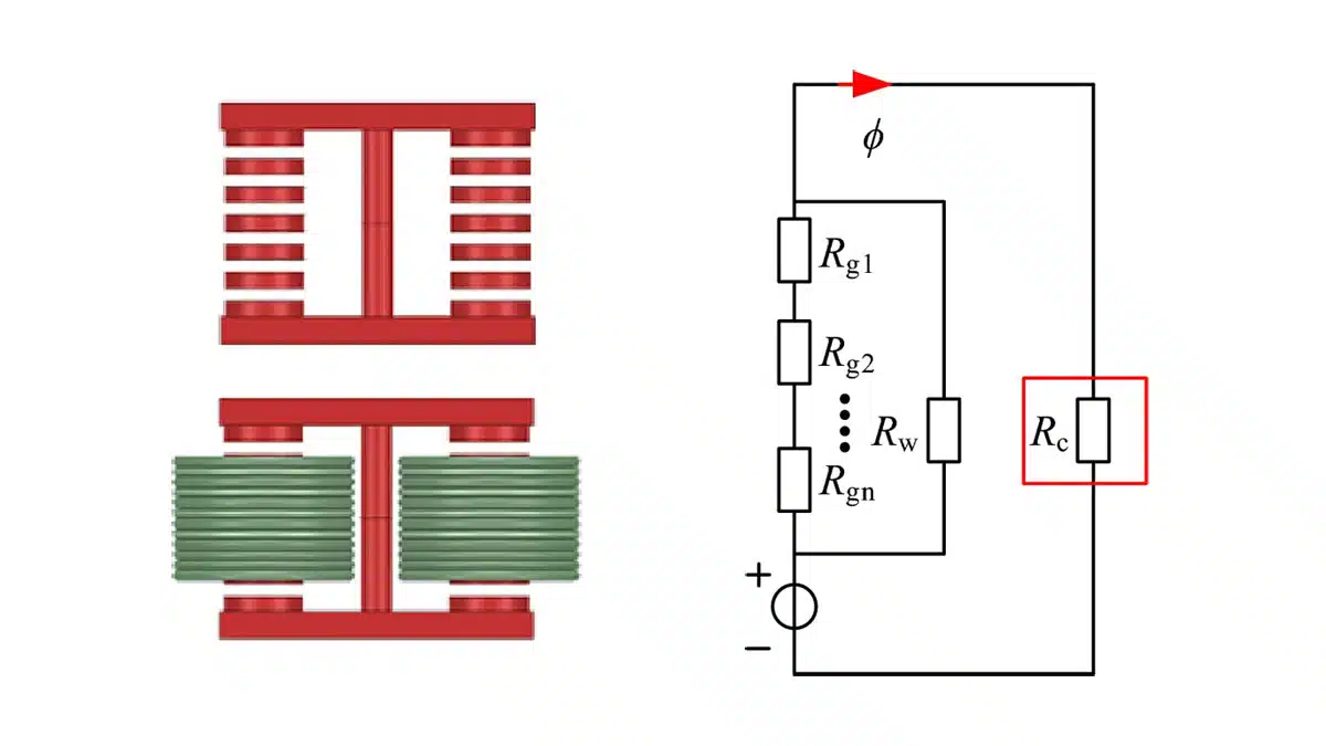
The reluctance model of the discrete inductor is chosen to calculate the winding reluctance. When the number of turns and the current in the winding are determined, the magnitude of the magnetic flux in the entire winding section can be obtained.

This paper will adopt a calculation method similar to that used for calculating transformer leakage inductance to calculate the winding magnetic flux accurately. When the magnetic flux inside the winding is uniformly and parallelly distributed. Since the diffusion reluctance of the air gap has been considered when calculating the air gap reluctance, the influence of the diffusion magnetic field of the air gap can now be ignored.

Air gap calculation

Based on the calculated formulas for air gap reluctance and winding reluctance from the previous analysis, an equivalent magnetic circuit for the inductor needs to be established to determine the length of each air gap. Assuming a uniform distribution of air gaps and equal size for each segment of the air gap.

Simulation and experimental validation

The 3D simulation models for the discrete inductor and the decoupled integrated inductor were created. The accuracy of the air gap length calculation method is verified through the simulation of the two inductor models. When the inductance value is known, the size of each segment of the air gap under different analyses is calculated and compared with the simulation results. Additionally, the method is validated for different inductance values. Finally, the error of this calculation method is obtained, confirming the correctness of the calculation method.

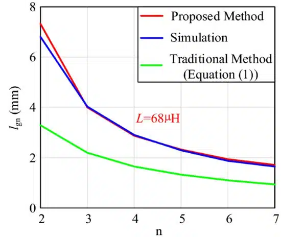
The comparison between the results of the proposed calculation method, the Maxwell simulation and the traditional method under different segments are shown in Figure 1. The Figure 1. shows the variation of the calculated and simulated air gap results with n when the inductance value is known.

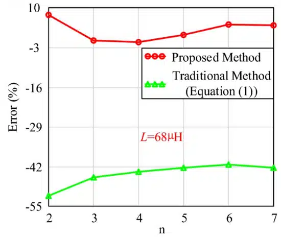
As the number of air gap segments increases, the length of each segment decreases. Meanwhile, the calculation errors at different numbers of air gap segments are shown in Fig. 2. The results indicate a good agreement between the proposed calculated and simulated results, demonstrating the high accuracy of the proposed calculation method. 

Figure 1. Results of the proposed inductor air gap calculation method, simulation results of different segments (L = 68 µH).
Figure 2. Calculation errors (L = 68 µH).

Conclusion

This paper delves into the application of the reluctance model for accurately calculating the air gap in inductors, particularly under conditions of a large air gap, using a distributed air gap approach. The focus is on discrete and decoupled integrated inductors within the context of bidirectional two-channel DC–DC converters.

By employing electromagnetic field theory, models for both air gap and winding reluctance are established. This includes a division of air gap reluctance into inner and diffusion components, with a specific emphasis on defining the radius of the air gap diffusion effect, a critical factor in determining air gap length. In the process of calculating winding reluctance, the air gap diffusion field is notably omitted, and the Rogowski factor is introduced to ascertain the equivalent winding height.

Additionally, the paper posits that air gap diffusion reluctance can be equated to both ring and ring shell forms, highlighting its significance in influencing the overall air gap diffusion reluctance and the precision of air gap length calculations. Comparative analysis of calculated air gap lengths, based on both discrete and decoupled integrated inductors, against simulated and measured results, is presented.

The findings indicate that the discrepancy between calculated and simulated values is less than 8%, with a minimum error margin of − 0.79%, under both constant and variable inductance conditions. Compared with traditional methods, the calculation method proposed in this paper has significant advantages. The error margin between calculated and measured values stands at − 1.11%. The concluding part of the paper confirms the validity and utility of the theoretical framework and the proposed calculation method through simulation and experimental results.

Read the full paper:

Zeng, X., Chen, W., Yang, L. et al. An accurate calculation method for inductor air gap length in high power DC–DC converters. Sci Rep 14, 3473 (2024). https://doi.org/10.1038/s41598-024-54194-7

Related

Source: Nature

Recent Posts

Bourns Extends Multilayer Chip Inductors Offer for RF and Wireless Designs

20.2.2026
7

Würth Elektronik Component Data Live in Accuris

19.2.2026
14

Coilcraft Releases Automotive Common Mode Chokes

19.2.2026
10

2026 Power Magnetics Design Trends: Flyback, DAB and Planar

13.2.2026
46

Vishay Releases Compact 0806 Low‑DCR Power Inductor

5.2.2026
34

Murata Publishes Power Delivery Guide for AI Servers

4.2.2026
126

Selecting Current Sense Transformers with Würth Elektronik REDEXPERT

3.2.2026
36

Mechanical Drift Indicator of Tantalum Capacitor Anodes Degradation under Reverse Bias

3.2.2026
50

Enabling Software‑Defined Vehicle Architectures: Automotive Ethernet and Zonal Smart Power

2.2.2026
43

Upcoming Events

Feb 24
16:00 - 17:00 CET

Mastering Galvanic Isolation: Ensuring Safety in Power Electronics

Mar 3
16:00 - 17:00 CET

Cybersecurity at the Eleventh Hour – from RED to CRA – Information and Discussion

Mar 21
All day

PSMA Capacitor Workshop 2026

View Calendar

Popular Posts

  • Buck Converter Design and Calculation

    0 shares
    Share 0 Tweet 0
  • Boost Converter Design and Calculation

    0 shares
    Share 0 Tweet 0
  • LLC Resonant Converter Design and Calculation

    0 shares
    Share 0 Tweet 0
  • Flyback Converter Design and Calculation

    0 shares
    Share 0 Tweet 0
  • Ripple Current and its Effects on the Performance of Capacitors

    3 shares
    Share 3 Tweet 0
  • Dual Active Bridge (DAB) Topology

    0 shares
    Share 0 Tweet 0
  • What is a Dielectric Constant and DF of Plastic Materials?

    4 shares
    Share 4 Tweet 0
  • MLCC and Ceramic Capacitors

    0 shares
    Share 0 Tweet 0
  • MLCC Case Sizes Standards Explained

    0 shares
    Share 0 Tweet 0
  • SEPIC Converter Design and Calculation

    0 shares
    Share 0 Tweet 0

Newsletter Subscription


Passive Components Blog

© EPCI - Leading Passive Components Educational and Information Site

  • Home
  • Privacy Policy
  • EPCI Membership & Advertisement
  • About

No Result
View All Result
  • Home
  • Knowledge Blog
  • PCNS

© EPCI - Leading Passive Components Educational and Information Site

This website uses cookies. By continuing to use this website you are giving consent to cookies being used. Visit our Privacy and Cookie Policy.
Go to mobile version