


In many applications reliability, stability and long lifetime of resistors are of critical importance. Lets learn something about resistors’ noise and corrosion.
Key Takeaways
- Resistors play a critical role in electronics, influencing reliability and performance due to their noise and corrosion characteristics.
- Noise in resistors, including thermal and current noise, affects signal quality and varies by resistor type and application.
- Electrical corrosion can lead to resistance drift and failures, caused by moisture and contamination in the environment.
- Effective design guidelines focus on selecting appropriate resistor technologies and implementing protective measures against corrosion and leakage.
- Understanding resistors’ noise and corrosion helps improve robustness and precision in high-reliability applications.
In precision and long‑lifetime electronics, resistors are often the hidden limiters of performance and reliability. This guide expands basic concepts of resistor noise and electrical corrosion into practical design rules, examples, and selection guidance for real‑world applications.
1. Fundamentals of Noise in Resistors
Noise in resistors appears as a randomly fluctuating voltage or current superimposed on the ideal DC or AC signal. In practice, we work with time‑averaged quantities, typically as root mean square (RMS) values over a defined bandwidth.
Key points:
- Noise is characterized statistically (mean‑square or RMS), not by instantaneous values.
- The relevant quantity for design is usually noise spectral density (per Hz) integrated over a bandwidth of interest.
- Different physical mechanisms dominate in different technologies and frequency ranges.
2. Thermal Noise (Johnson‑Nyquist Noise)
Thermal noise is caused by the thermally agitated charge carriers in the resistive material. It exists in every resistor, regardless of technology, and depends only on absolute temperature, resistance value, and measurement bandwidth.
The RMS noise voltage across a resistor is given bywhere is Boltzmann’s constant, absolute temperature, resistance, and the bandwidth.
Implications for design:
- Thermal noise is independent of resistor type: thick film, thin film, wirewound, or carbon composition all share the same thermal‑noise level for the same , and
- To reduce thermal noise: decrease resistance, reduce bandwidth, or lower temperature where feasible.
- Thermal noise typically dominates at high frequencies where excess/current noise becomes negligible.
3. Excess / Current Noise
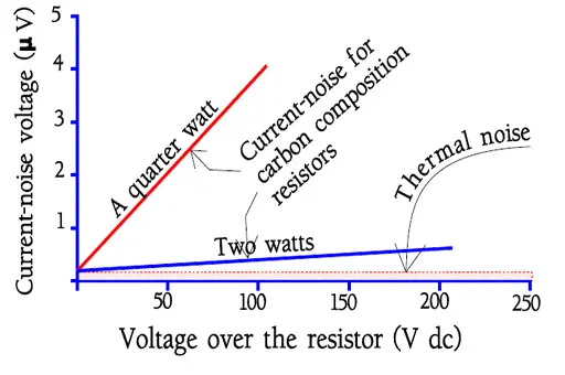
When a DC current flows through a resistor, additional noise appears beyond the thermal component. This is commonly called current noise, excess noise, or ‑like noise depending on context.
3.1 Physical Origin
Current noise is especially pronounced in resistive structures formed by granular or non‑uniform conduction paths, such as carbon composition or certain film resistors. Local changes in contact area and conductivity at grain boundaries and defects create random fluctuations in resistance under bias, which translate into noise voltage.
Even in metal wires and films, current noise exists but is usually negligible for most applications compared to granular materials.
3.2 Frequency and Voltage Dependence
For many resistor technologies, current noise:
- Is approximately proportional to applied DC voltage.
- Shows an approximate dependence on frequency.
- Becomes negligible above roughly 10 kHz in many practical applications.
As a rule of thumb, each frequency decade contains roughly the same contribution to total current noise in ‑dominated regimes.
4. Noise Metrics and Standards
Because noise is a statistical quantity, standardized measurement conditions are essential. Typical standards specify bias, resistance range, and measurement bandwidth.
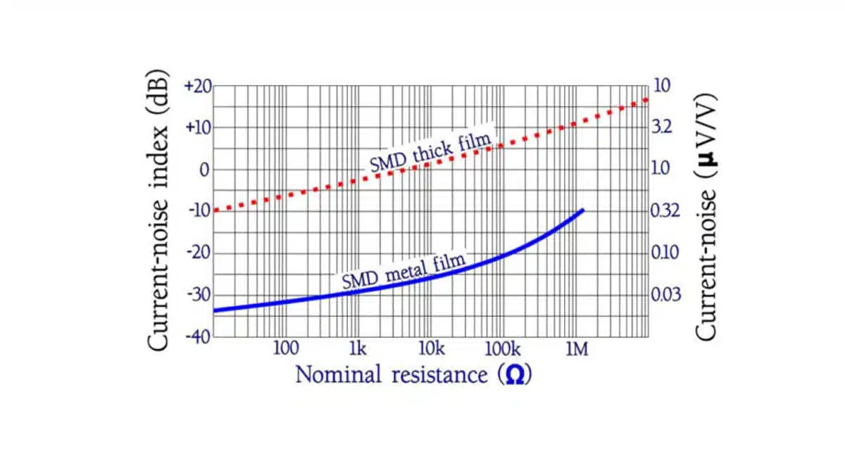
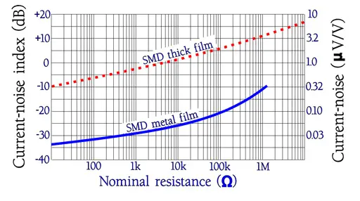
4.1 Noise Index
One widely used figure of merit is the noise index (NI):
- Defined as noise voltage in microvolts per volt of applied DC, per frequency decade, often expressed in dB.
- Lower NI indicates a lower‑noise resistor technology for the same operating conditions.
You can treat NI as a comparative selection metric across resistor series and technologies within the same resistance value range.
4.2 Practical Interpretation
Typical qualitative trends:
- Carbon composition and standard thick‑film resistors generally have higher noise index.
- Thin‑film, metal‑foil, and good wirewound resistors exhibit very low excess noise, often negligible compared to thermal noise in many applications.
5. Typical Noise Performance by Technology
The table below gives a qualitative view of relative excess‑noise behavior of common resistor technologies at low frequencies under DC bias.
| Resistor technology | Excess noise level (qualitative) | Typical use cases |
|---|---|---|
| Carbon composition | High | Legacy designs, surge‑tolerant but noisy applications |
| Carbon film | Medium–high | General purpose where noise is not critical |
| Thick film (SMD) | Medium | General electronics, digital, non‑critical analog |
| Metal film (axial) | Low | Precision analog, audio, instrumentation |
| Thin film (SMD) | Very low | Precision, low‑noise front ends, A/D references |
| Metal foil | Extremely low | Ultra‑low noise and high stability applications |
| Wirewound | Very low | Precision, power shunts, low‑frequency analog |
This table is qualitative and exact values depend on manufacturer and series.
6. Design Guidelines for Low‑Noise Circuits
To design for low noise, treat the resistor as part of the entire signal chain rather than in isolation.
Key guidelines:
- Use the lowest resistance value consistent with signal level and loading constraints to reduce thermal noise.
- Prefer thin‑film, metal‑film, or foil resistors in low‑level analog front ends, audio inputs, and sensor interfaces.
- Keep bandwidth limited to what the application truly needs using proper filtering.
- Avoid high‑value carbon or thick‑film resistors in the first stages of precision amplifiers when DC bias is present.
Example: In a low‑level audio preamplifier input, replacing a high‑value thick‑film SMD bias resistor with a lower‑value thin‑film part often yields a measurable improvement in hiss and background noise.
7. Layout and Measurement Considerations
Resistor noise interacts with layout‑dependent parasitics and external interference. Good PCB practice is essential to realize the theoretical performance of chosen components.
7.1 Layout
- Keep high‑impedance nodes short and shielded to minimize capacitive coupling and induced noise.
- Use ground planes and proper star‑grounding in sensitive analog areas.
- Avoid routing digital or high‑current traces parallel and close to low‑level analog resistors.
7.2 Measurement
Measuring low noise requires instrumentation whose own noise floor is well below the device under test.
- Use low‑noise amplifiers and spectrum analyzers with known input‑referred noise.
- Calibrate using known reference resistors and compare against calculated thermal noise.
- Follow standardized bandwidth definitions when reporting noise measurements.
8. Electrical Corrosion in Resistors
Electrical corrosion in resistors arises when moisture and ionic contamination create conductive electrolyte paths between metallic and resistive structures under electrical bias. This can cause resistance drift, increased leakage, or complete open‑circuit failures over time.
Mechanism
In the presence of a thin film of moisture containing dissolved ions:
- DC voltage drives electrochemical reactions at metal interfaces.
- Anodic areas can corrode or dissolve, while cathodic areas may see deposition or hydrogen evolution.
- Localized material loss and chemical changes modify the conduction path and eventually lead to failure.
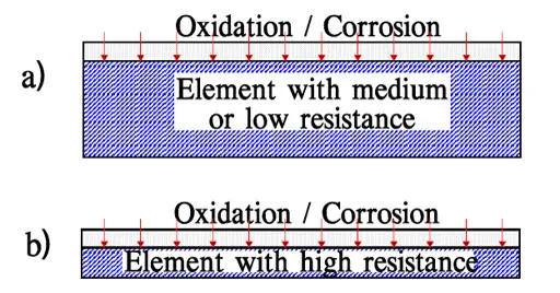
High‑ohmic and thin‑film structures are particularly sensitive because their current paths are narrow and any local material loss can significantly increase resistance.
9. Environmental and Application Factors
The likelihood and speed of corrosion‑related failures depend strongly on environmental conditions.
Major factors:
- Relative humidity and condensation, especially cyclic humidity.
- Temperature, which accelerates chemical reactions and diffusion.
- Contaminants such as flux residues, salts, industrial pollutants, and sulfur‑bearing gases.
- Applied DC bias and its polarity relative to sensitive structures.
Applications in industrial atmospheres, coastal environments, or under‑hood automotive positions experience significantly harsher conditions than controlled indoor equipment.
10. Construction, Materials, and Corrosion Robustness
Resistor construction has a strong influence on corrosion behavior.
Important aspects:
- Resistive element type (carbon film, metal film, thick film, metal‑glaze, wirewound).
- Termination materials (Cu, Ni, Ag, Ag‑Pd, Sn) and their galvanic potential differences.
- Protective coatings and encapsulation, from simple lacquer to molded epoxy or glass.
- Package style (SMD chip vs. leaded) and accessibility of terminations and resistive paths to the environment.
Metal‑glaze and properly protected metal‑film resistors are generally more resistant to aqueous corrosion than unprotected granular or porous structures exposed to moisture.
11. Test Methods and Reliability Metrics
Corrosion and moisture sensitivity are commonly evaluated using biased humidity tests and related accelerated methods.
Typical approaches:
- Temperature‑humidity‑bias tests, where resistors are powered under high humidity and elevated temperature for extended durations.
- Highly accelerated stress tests for faster screening of weak constructions.
- Sulfur exposure tests for environments containing sulfur compounds, relevant for some thick‑film and silver‑containing terminations.
Results are usually expressed as resistance change distributions, number of failures, and time to specified drift thresholds.
12. Design Guidelines Against Corrosion and Leakage
Corrosion and moisture‑induced leakage can be mitigated by proper component selection, board design, and manufacturing processes.
Key guidelines:
- Choose corrosion‑resistant resistor technologies (for example, metal‑glaze, high‑quality metal film, sulfur‑resistant series) for harsh environments.
- Avoid unnecessarily high resistance values in locations exposed to humidity and contamination; high‑ohmic paths are more affected by leakage and surface films.
- Use conformal coating or encapsulation in high‑humidity or polluted environments to minimize moisture access.
- Control board cleanliness: use appropriate fluxes, thoroughly wash if required, and verify ionic contamination levels.
- Maintain sufficient creepage and clearance distances and avoid sharp edges and contamination traps in PCB layout.
13. Application Mapping Table
The table below gives a qualitative mapping from typical environment to recommended resistor technologies and protective measures.
| Environment / application | Typical stressors | Recommended resistor types | Extra measures |
|---|---|---|---|
| Consumer indoor electronics | Mild temperature, low humidity | Thick film SMD, metal film axial | Standard cleaning, no special coating |
| Industrial control (indoor) | Elevated temp, moderate humidity, pollution | Metal film, robust thick film, metal‑glaze | Good cleaning, optional coating |
| Outdoor telecom / base stations | Humidity, condensation, pollution, salt spray | Metal‑glaze, high‑reliability metal film | Conformal coating, spacing, sealing |
| Automotive cabin | Temp cycling, moderate humidity | Thick film SMD, metal film, automotive‑grade | Automotive‑qualified parts |
| Automotive under‑hood | High temp, humidity, splash, pollutants | Metal‑glaze, robust thick film, wirewound | Coating, sealing, validated THB tests |
| Industrial sulfurous atmosphere | Sulfur gases, humidity | Sulfur‑resistant thick film or metal‑glaze | Use sulfur‑resistant series, coating |
This mapping is indicative only and should be refined using specific component series data and qualification results.
14. Conclusion
Resistors are more than simple ohmic elements; their intrinsic noise and vulnerability to electrical corrosion can limit both the performance and lifetime of modern electronics. By understanding the underlying noise mechanisms, choosing an appropriate resistor technology, and applying sound layout and environmental protection practices, designers can significantly improve system robustness and precision.
A structured selection process that considers noise, environment, and construction simultaneously is essential, especially in high‑reliability and low‑signal‑level applications. Complementing this with proper testing and qualification closes the loop between theoretical design and long‑term field performance.
FAQ – Resistors Noise and Corrosion
The main types are thermal (Johnson‑Nyquist) noise, which depends on temperature, resistance and bandwidth, and excess or current noise, which appears under DC bias and often follows a 1/f frequency dependence.
Carbon composition, carbon film, and standard thick‑film resistors exhibit relatively high excess noise, while metal film, thin film, metal foil, and wirewound resistors provide low to extremely low excess noise suitable for precision and low‑level analog applications.
Noise index is a figure of merit that expresses noise voltage per applied DC volt per frequency decade, usually in microvolts or dB, and it serves as a comparative parameter to select lower‑noise resistor series and technologies.
Key practices include using the lowest practical resistance values, limiting bandwidth with proper filtering, and selecting thin‑film, metal‑film, or foil resistors in sensitive analog front ends instead of high‑value carbon or thick‑film parts under DC bias.
Electrical corrosion occurs when moisture and ionic contamination form an electrolyte path between metallic and resistive structures under DC bias, driving electrochemical reactions that change the conduction path and can lead to resistance drift or open‑circuit failure.
High relative humidity, condensation, elevated temperature, surface contamination such as flux residues and salts, industrial pollutants including sulfur‑bearing gases, and sustained DC bias significantly increase the risk and speed of corrosion‑related failures.
Metal‑glaze and well‑protected metal‑film resistors with suitable termination materials, robust coatings, or molded encapsulation typically offer better corrosion resistance than unprotected granular or porous structures exposed directly to moisture.
Manufacturers use temperature‑humidity‑bias tests, highly accelerated stress tests, and sulfur exposure tests to evaluate resistance drift, leakage, and failure rates under harsh environmental and electrical conditions.
Designers should choose corrosion‑resistant resistor technologies, avoid very high resistance values in humid or contaminated locations, apply conformal coating in harsh environments, ensure good board cleanliness, and maintain adequate creepage and clearance distances on the PCB.
How to design resistor circuits that minimize electrical noise and reduce the risk of corrosion and leakage in demanding environments.
- Select resistor values for low thermal noise
Start by choosing the lowest resistance values that still meet your signal level, loading, and power dissipation constraints, because thermal noise voltage scales with resistance and measurement bandwidth.
- Choose suitable low‑noise resistor technologies
For low‑level analog, audio, and precision sensor interfaces, prefer thin‑film, metal‑film, metal‑foil, or good wirewound resistors instead of high‑noise carbon composition, carbon film, or standard thick‑film parts.
- Limit circuit bandwidth to what is necessary
Add appropriate filtering so that the signal chain only passes the bandwidth required by the application, which directly reduces integrated thermal and excess noise.
- Optimize PCB layout for low noise
Keep high‑impedance nodes short and shielded, use solid ground planes or star‑grounding in sensitive analog sections, and avoid routing noisy digital or high‑current traces parallel to low‑level resistor nodes.
- Assess the operating environment for corrosion risk
Identify whether the application will face high humidity, condensation, temperature cycling, salt spray, industrial pollutants, or sulfur‑rich atmospheres, as these conditions strongly influence corrosion behaviour.
- Select corrosion‑resistant resistor series
In harsh environments such as outdoor telecom, industrial control, or automotive under‑hood locations, use metal‑glaze, high‑reliability metal‑film, robust thick‑film, or sulfur‑resistant resistor series qualified for biased humidity and sulfur tests.
- Control leakage paths on the PCB
Avoid excessively high resistance values where moisture or contamination may be present, maintain sufficient creepage and clearance distances, and design pads and traces to minimize surface leakage paths.
- Improve board cleanliness and protection
Use suitable flux systems, ensure thorough cleaning or washing when required, verify low ionic contamination levels, and consider conformal coating or encapsulation for high‑humidity or polluted environments.
- Verify performance with appropriate testing
Validate your design using noise measurements with low‑noise instrumentation, and review supplier data or qualification results from temperature‑humidity‑bias, accelerated stress, and sulfur exposure tests.


