Passive Components Blog
No Result
View All Result
  • Home
  • NewsFilter
    • All
    • Aerospace & Defence
    • Antenna
    • Applications
    • Automotive
    • Capacitors
    • Circuit Protection Devices
    • electro-mechanical news
    • Filters
    • Fuses
    • Inductors
    • Industrial
    • Integrated Passives
    • inter-connect news
    • Market & Supply Chain
    • Market Insights
    • Medical
    • Modelling and Simulation
    • New Materials & Supply
    • New Technologies
    • Non-linear Passives
    • Oscillators
    • Passive Sensors News
    • Resistors
    • RF & Microwave
    • Telecommunication
    • Weekly Digest

    Experimental Evaluation of Wear Failures in SMD Inductors

    Resonant Capacitors in High-Power Resonant Circuits

    a Schematic diagram of the BNT-based components constructed based on the entropy-increase strategy. b Digital photograph, cross-sectional SEM image, and EDS mappings of the MLCCs. c Unipolar P-E loops of MLCCs as a function of applied E. d Wrec and η of the MLCCs as a function of applied E. The comparison of (e) Wrec and η, (f) η and UF of the MLCCs with those of other recently reported state-of-the-art MLCCs. source: Nature Communications

    Researchers Proposed Enhanced Energy Storage MLCC

    Littelfuse Releases First Reflow-Compatible Illuminated Tactile Switch

    Vishay Unveils 5W Power Metal Strip Resistor in Compact 1206 Case Size

    Improving SMPS Performance with Thermal Interface Material

    Polymer Tantalum Capacitors Beyond AEC-Q200 LEO Satellites

    Components Thermal and Frequency Challenges in 6G Base Stations

    Development of Nitrogen-Doped Graphene Supercapacitors 

    Trending Tags

    • Ripple Current
    • RF
    • Leakage Current
    • Tantalum vs Ceramic
    • Snubber
    • Low ESR
    • Feedthrough
    • Derating
    • Dielectric Constant
    • New Products
    • Market Reports
  • VideoFilter
    • All
    • Antenna videos
    • Capacitor videos
    • Circuit Protection Video
    • Filter videos
    • Fuse videos
    • Inductor videos
    • Inter-Connect Video
    • Non-linear passives videos
    • Oscillator videos
    • Passive sensors videos
    • Resistor videos

    Efficient Power Converters: Duty Cycle vs Conduction Losses

    Ripple Steering in Coupled Inductors: SEPIC Case

    SEPIC Converter with Coupled and Uncoupled Inductors

    Coupled Inductors in SEPIC versus Flyback Converters

    Non-Linear MLCC Class II Capacitor Measurements Challenges

    Percolation Phenomenon and Reliability of Molded Power Inductors in DC/DC converters

    Root Causes and Effects of DC Bias and AC in Ceramic Capacitors

    How to Calculate the Output Capacitor for a Switching Power Supply

    Switched Capacitor Converter Explained

    Trending Tags

    • Capacitors explained
    • Inductors explained
    • Resistors explained
    • Filters explained
    • Application Video Guidelines
    • EMC
    • New Products
    • Ripple Current
    • Simulation
    • Tantalum vs Ceramic
  • Knowledge Blog
  • Suppliers
    • Who is Who
  • Events
No Result
View All Result
Passive Components Blog
No Result
View All Result

Resonant Capacitors in High-Power Resonant Circuits

1.10.2025
Reading Time: 4 mins read
A A

The paper “Resonant Capacitors in High-Power Resonant Circuits” was presented by Moaz ElGhazali, Murata Electronics Europe B.V. Germany, Nürnberg, Germany at the 5th PCNS Passive Components Networking Symposium 9-12th September 2025, Seville, Spain as paper No. 5.4.

Introduction

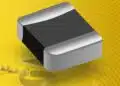
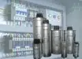
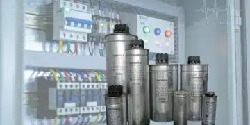
The paper “Resonant Capacitors in High-Power Resonant Circuits” focuses on the increasing use of multilayer ceramic capacitors (MLCCs) in high-power resonant applications such as automotive onboard chargers (OBCs), server power supplies, and large-scale wireless power transfer (WPT) systems.

RelatedPosts

Experimental Evaluation of Wear Failures in SMD Inductors

Improving SMPS Performance with Thermal Interface Material

Polymer Tantalum Capacitors Beyond AEC-Q200 LEO Satellites

It emphasizes how MLCCs ceramic capacitors can replace traditional film capacitors due to their compact size, superior high-frequency performance, low loss, and robust long-term reliability.

Murata Electronics introduces its 630 Vdc and 1000 Vdc MLCC product lines, highlighting their advantages and providing engineers with a selection tool, “Simsurfing,” to simplify capacitor choice and configuration.

Key Points

  • High adoption of resonant circuits in electric vehicles (EVs), plug-in hybrid vehicles (PHVs), and wireless power transfer systems.
  • MLCC advantages over film capacitors include smaller footprint, lower heat generation, and improved thermal and electrical performance.
  • Technical requirements focus on high voltage handling, high-frequency capability, low dielectric loss, and long-term reliability.
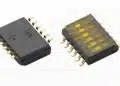
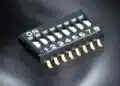
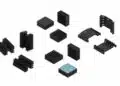
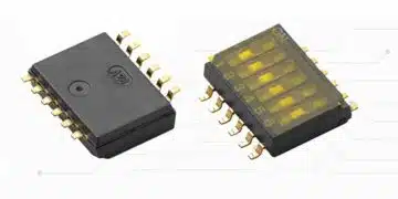
  • Murata MLCC lineup supports both standard and metal-terminal packages, with capacitance values up to 54 nF and operating temperatures from −55 to +125°C.
  • Voltage derating and self-heating are critical in selecting and configuring MLCCs to ensure longevity and safe operation.
  • Simsurfing selection tool offers automated recommendations for MLCCs and their optimal series–parallel networks.

Extended Summary

Recent developments in electric vehicles and wireless power transfer have driven the adoption of resonant circuits in power conversion systems to over 90%. LLC and LC topologies improve power efficiency, reduce filter requirements, and allow high-frequency operation. These conditions place stringent demands on resonant capacitors, which must sustain high peak-to-peak voltages, tolerate elevated temperatures, and exhibit low dielectric losses.

MLCCs are positioned as a superior alternative to film capacitors for such scenarios. Their compact form factor allows series–parallel network configurations to achieve high voltage ratings without occupying excessive space. In comparison to film capacitors, MLCCs offer three times smaller footprints, lower ESR and ESL, and better self-heating properties, which enhance efficiency in resonant circuits operating from 60 kHz to 400 kHz.

Technical requirements include stable capacitance above 10 nF, low losses under high-frequency excitation, and the ability to maintain surface temperatures below 125°C throughout a 10-year operational life. Murata addresses these needs with standard chip MLCCs and metal-terminal MLCCs. The latter reduces solder-crack risk in automotive environments and supports capacitance up to 54 nF. Both variants rely on C0G dielectric, which ensures exceptional thermal stability (0 ±30 ppm/°C from 25 to 125°C).

Voltage derating is essential to prevent excessive self-heating. The paper categorizes operating frequencies into three ranges, each with specific derating behavior: below 10 kHz where rated voltage governs, 10–100 kHz where continuous thermal rise limits operation, and above 100 kHz where initial heating constrains voltage application. Detailed derating charts guide engineers in applying optimal series–parallel configurations for reliable long-term service.

Murata’s “Simsurfing” web tool significantly eases the selection process by allowing engineers to input frequency, voltage, temperature, and required capacitance. It then suggests suitable MLCC products and network arrangements, ensuring both performance and durability in demanding resonant applications.

Conclusion

MLCCs are highly suitable for modern high-power resonant circuits due to their compact size, low loss, superior thermal properties, and long-term reliability. By following proper series–parallel configurations and adhering to voltage derating guidelines, engineers can confidently replace film capacitors with MLCCs. Murata’s comprehensive MLCC lineup, combined with the “Simsurfing” selection tool, offers a streamlined approach to optimize resonant circuit design and enhance system efficiency.

5_4_Murata_Resonant Capacitors_MoazDownload

Related

Source: PCNS

Recent Posts

Experimental Evaluation of Wear Failures in SMD Inductors

1.10.2025
2
a Schematic diagram of the BNT-based components constructed based on the entropy-increase strategy. b Digital photograph, cross-sectional SEM image, and EDS mappings of the MLCCs. c Unipolar P-E loops of MLCCs as a function of applied E. d Wrec and η of the MLCCs as a function of applied E. The comparison of (e) Wrec and η, (f) η and UF of the MLCCs with those of other recently reported state-of-the-art MLCCs. source: Nature Communications

Researchers Proposed Enhanced Energy Storage MLCC

1.10.2025
2

Littelfuse Releases First Reflow-Compatible Illuminated Tactile Switch

1.10.2025
1

Vishay Unveils 5W Power Metal Strip Resistor in Compact 1206 Case Size

1.10.2025
2

Improving SMPS Performance with Thermal Interface Material

30.9.2025
5

Polymer Tantalum Capacitors Beyond AEC-Q200 LEO Satellites

30.9.2025
16

Components Thermal and Frequency Challenges in 6G Base Stations

30.9.2025
8

Development of Nitrogen-Doped Graphene Supercapacitors 

30.9.2025
6

Layer-by-Layer Fabrication of Thin Polypropylene-based Dielectrics

30.9.2025
18

Reliability of E-Textile Conductive Paths and Passive Component Interfaces

29.9.2025
16

Upcoming Events

Sep 30
September 30 @ 12:00 - October 2 @ 14:00 EDT

MIL-Std-883 TM 2010

Oct 8
11:00 - 12:00 CEST

PCB Online Shop – simply “Made in Germany” by Würth Elektronik

Oct 14
16:00 - 17:00 CEST

Smart Sensors, Smarter AI: Building Reliable Edge Systems

Oct 17
12:00 - 14:00 EDT

External Visual Inspection per MIL-STD-883 TM 2009

Oct 20
October 20 - October 23

Digital WE Days 2025 – Virtual Conference

View Calendar

Popular Posts

  • Buck Converter Design and Calculation

    0 shares
    Share 0 Tweet 0
  • Boost Converter Design and Calculation

    0 shares
    Share 0 Tweet 0
  • Flyback Converter Design and Calculation

    0 shares
    Share 0 Tweet 0
  • LLC Resonant Converter Design and Calculation

    0 shares
    Share 0 Tweet 0
  • Dual Active Bridge (DAB) Topology Explained

    0 shares
    Share 0 Tweet 0
  • SEPIC Converter Design and Calculation

    0 shares
    Share 0 Tweet 0
  • What is a Dielectric Constant and DF of Plastic Materials?

    4 shares
    Share 4 Tweet 0
  • Ripple Current and its Effects on the Performance of Capacitors

    3 shares
    Share 3 Tweet 0
  • MLCC and Ceramic Capacitors

    0 shares
    Share 0 Tweet 0
  • Flying Capacitors Explained

    0 shares
    Share 0 Tweet 0

Newsletter Subscription


Passive Components Blog

© EPCI - Leading Passive Components Educational and Information Site

  • Home
  • Privacy Policy
  • EPCI Membership & Advertisement
  • About

No Result
View All Result
  • Home
  • Knowledge Blog
  • Premium Suppliers

© EPCI - Leading Passive Components Educational and Information Site

This website uses cookies. By continuing to use this website you are giving consent to cookies being used. Visit our Privacy and Cookie Policy.
Go to mobile version