Passive Components Blog
No Result
View All Result
  • Home
  • NewsFilter
    • All
    • Aerospace & Defence
    • Antenna
    • Applications
    • Automotive
    • Capacitors
    • Circuit Protection Devices
    • electro-mechanical news
    • Filters
    • Fuses
    • Inductors
    • Industrial
    • Integrated Passives
    • inter-connect news
    • Market & Supply Chain
    • Market Insights
    • Medical
    • Modelling and Simulation
    • New Materials & Supply
    • New Technologies
    • Non-linear Passives
    • Oscillators
    • Passive Sensors News
    • Resistors
    • RF & Microwave
    • Telecommunication
    • Weekly Digest

    TDK Releases Ultra-small PFC Capacitors

    KYOCERA AVX Releases Novel Mini BME Stacked Ceramic Capacitors

    Vishay Releases Class 1 Leaded High Voltage Ceramic Disc Capacitors

    TDK Releases 140C Compact Vibration Robust Automotive Aluminum Capacitors

    DigiKey Presents Factory Tomorrow Season 5 Video Series

    Samsung MLCCs Lineup for In-Vehicle Infotainment

    source: Samtec

    Best Practices for Cable Management in High-Speed and High-Density Systems

    Würth Elektronik Unveils Compact Common-Mode Data Lines Chokes

    Bourns Releases TCO 240 Watt USB Mini-Breaker

    Trending Tags

    • Ripple Current
    • RF
    • Leakage Current
    • Tantalum vs Ceramic
    • Snubber
    • Low ESR
    • Feedthrough
    • Derating
    • Dielectric Constant
    • New Products
    • Market Reports
  • VideoFilter
    • All
    • Antenna videos
    • Capacitor videos
    • Circuit Protection Video
    • Filter videos
    • Fuse videos
    • Inductor videos
    • Inter-Connect Video
    • Non-linear passives videos
    • Oscillator videos
    • Passive sensors videos
    • Resistor videos

    Ripple Steering in Coupled Inductors: SEPIC Case

    SEPIC Converter with Coupled and Uncoupled Inductors

    Coupled Inductors in SEPIC versus Flyback Converters

    Non-Linear MLCC Class II Capacitor Measurements Challenges

    Percolation Phenomenon and Reliability of Molded Power Inductors in DC/DC converters

    Root Causes and Effects of DC Bias and AC in Ceramic Capacitors

    How to Calculate the Output Capacitor for a Switching Power Supply

    Switched Capacitor Converter Explained

    Understanding Inductor Dot Markings and Their Application in LTspice

    Trending Tags

    • Capacitors explained
    • Inductors explained
    • Resistors explained
    • Filters explained
    • Application Video Guidelines
    • EMC
    • New Products
    • Ripple Current
    • Simulation
    • Tantalum vs Ceramic
  • Knowledge Blog
  • Suppliers
    • Who is Who
  • Events
No Result
View All Result
Passive Components Blog
No Result
View All Result

Rigid Flexible PCBs Construction

11.8.2025
Reading Time: 4 mins read
A A

This first part of Würth Elektronik PCB webinar on RIGID.flex technology is intended as an introduction to the production of rigid-flex PCBs and covers constructions with one or two external flex layers.

Rigid-flex printed circuit board is a very complex construct, produced by a large number of sequential processes from a wide variety of materials, which must also be suitable for further processing and the planned application. Understanding this helps in PCB design to be able to successfully implement the requirements from the functional specification in the design and the knowledge equally helps in communicating with the PCB manufacturer.

RelatedPosts

Würth Elektronik Unveils Compact Common-Mode Data Lines Chokes

SEPIC Converter with Coupled and Uncoupled Inductors

Würth Elektronik Releases Push-Button and Main Switches

In this webinar you will learn more about

  • The difference between flexible and rigid-flex printed circuit boards
  • The basic materials for RIGID.flex printed circuit boards
  • The relevant norms and standards
  • The manufacturing and production processes for rigid-flex with external flex layer
  • Application examples

Understanding Rigid-Flex PCB Technology

Introduction

Rigid-flex printed circuit boards (PCBs) offer a complex and versatile construction, combining the benefits of both rigid and flexible substrates. This article introduces the key aspects of Rigid-flex PCB technology, as presented in Würth Elektronik’s webinar, focusing on the production processes, materials involved, and structural configurations.

Key Concepts in Rigid-Flex PCB Design

1. Distinction Between Flexible and Rigid-Flex PCBs

  • Flexible PCBs (FPCs): Composed primarily of flexible base materials, allowing high integration density and miniaturization. They are characterized by their lack of rigid areas and partial stiffness, which is not electrically connected to the flex layers.
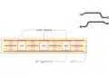
  • Rigid-Flex PCBs: These boards integrate rigid and flexible sections, connected through flexible base materials with through-plate connections. They typically include at least two copper layers, offering enhanced robustness and reliability.

Materials for Rigid-Flex PCB Construction

1. Flexible Base Materials

  • Polyimide Cores: Common thicknesses range from 25 to 100 microns.
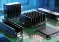
  • Copper Foils: Standard thicknesses are 18, 35, and 70 microns.
  • Adhesiveless Materials: Preferred for superior electrical properties.

2. Rigid Base Materials

  • FR4 and Prepregs: Traditional materials offering flame retardancy and mechanical stability.
  • Composite Materials: Include glass fabric pre-impregnated with resin, providing various thermal and mechanical properties.

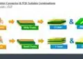
Manufacturing Process

The production of rigid-flex PCBs involves several sequential steps:

  1. Inner Layer Processing: Cleaning, laminating, exposure, developing, etching, and stripping to form circuit patterns.
  2. Mechanical Processing: Milling and routing to transition between rigid and flexible areas.
  3. Lamination: Combining multiple layers using thermal pressure.
  4. Drilling and Plating: Creating vias for electrical connections.
  5. Surface Finishing: Applying protective coatings and conducting electrical tests.
  6. Final Inspection: Ensuring quality before shipment.

Application Examples

Rigid-flex PCBs are utilized across industries such as aerospace, telecommunications, automotive, and consumer electronics. Their design supports miniaturization, dynamic movements, and system integration.

Design Considerations

Proper design rules are critical, especially for transitions between rigid and flexible sections. Key areas include maintaining electrical integrity, mechanical flexibility, and reliability in harsh environments.

Conclusion

Rigid-flex PCB technology represents a sophisticated solution for modern electronic applications. Understanding its materials, manufacturing processes, and design principles is essential for optimized performance and reliability.

Related

Source: Würth Elektronik

Recent Posts

Glass Core Technology Breakthrough Potential for High-Speed Interconnects

12.6.2025
50

What Track Width To Use When Routing PCB

6.6.2025
61

Highly Reliable Flex Rigid PCBs, Würth Elektronik Webinar

15.5.2025
49

High-Density PCB Assemblies For Space Applications

2.5.2025
52

IPC Class 2 vs Class 3 Solder Joints Requirements Explained

27.2.2025
502

HIROSE Expands Open Pluggable OPS PCB connector

9.1.2025
52

How to Determine Chip Temperature

3.1.2025
220

Die and Wire PCB Bonding Explained

1.7.2025
157

EMI Shielding Challenges

1.7.2025
15

EMC with Electromechanical Inter-Connections

1.7.2025
15

Upcoming Events

Sep 16
17:00 - 18:00 CEST

EMI Shielding Challenges

Sep 22
September 22 @ 13:00 - September 25 @ 15:15 EDT

Pre Cap Visual Inspection per Mil-Std-883 (TM 2017)

Sep 30
September 30 @ 12:00 - October 2 @ 14:00 EDT

MIL-Std-883 TM 2010

Oct 17
12:00 - 14:00 EDT

External Visual Inspection per MIL-STD-883 TM 2009

Oct 20
October 20 - October 23

Digital WE Days 2025 – Virtual Conference

View Calendar

Popular Posts

  • Buck Converter Design and Calculation

    0 shares
    Share 0 Tweet 0
  • Boost Converter Design and Calculation

    0 shares
    Share 0 Tweet 0
  • Flyback Converter Design and Calculation

    0 shares
    Share 0 Tweet 0
  • LLC Resonant Converter Design and Calculation

    0 shares
    Share 0 Tweet 0
  • Dual Active Bridge (DAB) Topology Explained

    0 shares
    Share 0 Tweet 0
  • Ripple Current and its Effects on the Performance of Capacitors

    3 shares
    Share 3 Tweet 0
  • What is a Dielectric Constant and DF of Plastic Materials?

    4 shares
    Share 4 Tweet 0
  • SEPIC Converter Design and Calculation

    0 shares
    Share 0 Tweet 0
  • How to Design an Inductor

    0 shares
    Share 0 Tweet 0
  • Core Materials, Permeability and Their Losses

    0 shares
    Share 0 Tweet 0

Newsletter Subscription


Passive Components Blog

© EPCI - Leading Passive Components Educational and Information Site

  • Home
  • Privacy Policy
  • EPCI Membership & Advertisement
  • About

No Result
View All Result
  • Home
  • Knowledge Blog
  • Premium Suppliers

© EPCI - Leading Passive Components Educational and Information Site

This website uses cookies. By continuing to use this website you are giving consent to cookies being used. Visit our Privacy and Cookie Policy.
Go to mobile version