


This article based on edited blog note from, Pablo Blázquez, Power Electronics Engineer at Frenetic, explains the physical mechanisms behind skin and proximity losses and examines how conductor geometry — Litz wire, round wire, rectangular wire, and foil conductors — influences winding loss performance in magnetics design.
Winding losses are one of the primary sources of power dissipation in transformers and inductors, directly affecting thermal behaviour, conversion efficiency, and component lifetime. While DC resistance losses are straightforward to calculate, AC winding losses — driven by skin effect and proximity effect — are frequency-dependent phenomena that can cause the effective winding resistance to rise several times above its DC value. This is especially critical in high-frequency power electronics applications such as LLC resonant converters, PFC boost stages, and wireless power transfer systems operating above 20 kHz.
The article explains specific effects that lead to these losses and temperature rise, with a particular focus on two key players: skin and proximity losses – see Figure 1. By understanding how they impact the efficiency and performance of our magnetic components, we will know how to combat these effects.
Key Takeaways
- Winding losses in transformers and inductors primarily arise from skin and proximity effects, which increase with frequency.
- Skin depth significantly decreases from ~8.5 mm at 60 Hz to ~0.21 mm at 100 kHz, influencing conductor selection.
- Proximity losses increase with the number of winding layers, leading to higher losses in multi-layer designs.
- Different conductor types, such as Litz wire, rectangular wire, and foil conductors, affect winding loss performance differently.
- To minimize winding losses, techniques include using appropriate wire types, reducing layer counts, and applying proper insulation.
Skin Losses
Skin losses — also referred to as skin effect losses — arise from the behaviour of alternating current in a conductor. As AC frequency increases, current progressively concentrates toward the outer surface of the wire rather than flowing uniformly across its cross-section. The inner conductor volume becomes underutilized, effectively reducing the usable cross-sectional area and increasing the winding’s AC resistance.
The depth to which current penetrates the conductor is described by the skin depth (δ):
δ = √(ρ / (π · f · μ))
Where ρ is the conductor resistivity (Ω·m), f is the operating frequency (Hz), and μ is the magnetic permeability of the conductor (H/m). For copper at 20°C, skin depth is approximately 8.5 mm at 60 Hz, but drops sharply to around 0.21 mm at 100 kHz. This means that in a standard 1 mm diameter copper wire, nearly all current is confined to a thin outer shell at 100 kHz — the bulk of the conductor contributes almost nothing to current conduction.
As temperature rises, copper resistivity increases (~0.4%/°C), which increases skin depth slightly but also raises overall winding resistance, creating a self-reinforcing thermal effect designers must account for during derating.
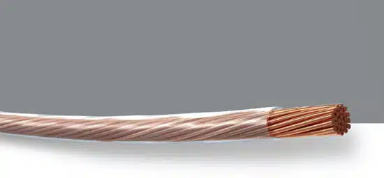
Minimising skin losses requires ensuring a more uniform current distribution across the conductor cross-section. The most effective solution at high frequencies is Litz wire, composed of multiple individually insulated strands, each thinner than the skin depth at the target operating frequency — ensuring that current is forced to distribute evenly across all strands.
Proximity Losses
Proximity losses are a second, often underestimated, component of AC winding losses. They occur when the alternating magnetic field generated by one winding induces eddy currents in a neighbouring conductor. These eddy currents flow in circular paths within the conductor and produce additional ohmic losses — even in a conductor carrying no net current of its own.
Unlike skin losses, which affect each conductor in isolation, proximity losses are a function of the magnetic environment around the conductor. In a tightly wound multi-layer coil, the cumulative magnetic field seen by each successive layer increases — and since proximity losses scale approximately with the square of the number of layers, a winding with 4 layers can experience proximity losses up to 16× higher than a single-layer winding, even at the same current level.
Key techniques for reducing proximity losses include:
- Winding interleaving — alternating primary and secondary winding layers to reduce the net MMF seen by each layer.
- Insulation and spacing — maintaining sufficient clearance between adjacent windings to reduce magnetic coupling.
- Reducing the number of winding layers — using wider conductors (foil or rectangular wire) rather than many turns of thin round wire.
- Litz wire — the insulation between strands limits eddy current paths between neighbouring conductors.
Understanding and addressing proximity losses is key to enhancing the efficiency and performance of our winding designs.
Wire Types Winding Losses Impact
Different types of wire configurations have varying impacts on both skin and proximity losses in Transformers and Inductors.
Litz Wire
As said before, it is composed of individually insulated strands woven together, which significantly reduces skin losses. Distributing the current more evenly across the wire mitigates the concentration of current on the outer surface, thereby minimizing energy dissipation. Additionally, proper insulation between the strands helps to reduce proximity losses by limiting magnetic coupling between adjacent windings.
💡 Design Rule of Thumb: For Litz wire, individual strand diameter should be no larger than twice the skin depth at the operating frequency. For copper at 100 kHz (δ ≈ 0.21 mm), use Litz strands ≤ 0.42 mm diameter.
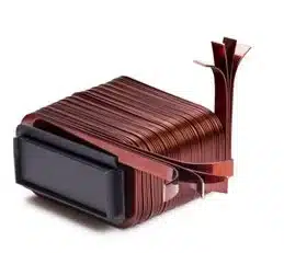
Rectangular Wires
They offer a favorable shape for reducing skin losses. The wider surface area allows for better current distribution, minimizing the concentration of current on the outer surface and reducing energy dissipation. Proximity losses can also be mitigated with careful positioning and insulation.
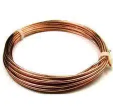
Round Wires
Round solid wire is the most common and cost-effective conductor type, well-suited for low-frequency applications such as mains-frequency (50/60 Hz) power transformers and line-frequency inductors. However, at higher frequencies, round wire performs poorly in terms of AC losses. Because current crowds into a thin outer annular ring (determined by the skin depth), the majority of the conductor cross-section is wasted — effectively increasing AC resistance. Additionally, the circular geometry and close packing of round conductors in a multi-layer winding can lead to strong magnetic coupling between adjacent turns, increasing proximity losses. Round wire is generally not recommended for designs operating above 10–20 kHz where winding loss is a performance-critical factor.
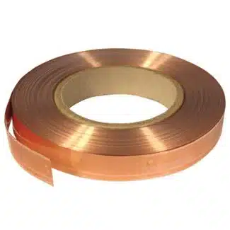
Foil Conductors
Composed of flat strips, they excel at reducing skin losses due to their larger surface area. The flattened shape provides improved current distribution and decreases energy dissipation. Proximity losses can be controlled by proper insulation and spacing between adjacent foil conductors.
| Conductor Type | Skin Loss Reduction | Proximity Loss Reduction | Typical Frequency Range | Relative Cost | Typical Application |
|---|---|---|---|---|---|
| Round Wire (solid) | Low | Low | < 5 kHz | Low | Mains transformers, low-frequency inductors |
| Rectangular Wire | Medium | Medium | 1 kHz – 100 kHz | Medium | Power inductors, toroidal cores |
| Foil Conductor | High | Medium* | 1 kHz – 50 kHz | Medium | Low-profile inductors, current transformers |
| Litz Wire | High | Medium–High | 10 kHz – 1 MHz | High | HF resonant converters, wireless charging, audio |
| PCB / Planar Winding | Medium (with design) | Medium–High (with interleaving) | 100 kHz – several MHz | Low (integrated) | Planar transformers, GaN/SiC power stages |
*Foil proximity losses can be significant between adjacent layers if not properly spaced or insulated.
By considering the characteristics of each wire type, such as the distribution of current and magnetic interactions, you can make mindful choices to optimize winding designs and minimize both skin and proximity losses. Understanding how these different wire configurations impact losses is vital for achieving enhanced efficiency in transformers and inductors.
Conclusion
Skin and proximity losses are the dominant AC winding loss mechanisms in transformers and inductors, and both become increasingly significant as switching or operating frequency rises. While DC copper losses are proportional to RDC and current squared, AC losses depend critically on conductor geometry, winding arrangement, and operating frequency — and can easily exceed DC losses by a factor of 5–10× in high-frequency designs.
Skin losses are governed by the skin depth, which for copper shrinks from millimetre scale at mains frequency to sub-millimetre at 100 kHz. Proximity losses, driven by eddy currents induced by neighbouring conductors, scale with the square of the number of winding layers and are therefore particularly problematic in multi-layer high-frequency windings.
Conductor selection — Litz wire, foil, rectangular, or round — must be matched to the operating frequency and winding geometry. Equally important are design techniques such as winding interleaving, layer reduction, and proper insulation to control the magnetic environment around each conductor.
For accurate AC loss prediction in complex geometries, numerical simulation tools such as FEMM (Finite Element Method Magnetics) or commercial platforms such as Frenetic’s online magnetics design tool should be
used alongside analytical methods, particularly for multi-layer windings in resonant converter applications.
References and Further Reading
- Functionality of Transformer and Solenoid – Passive Components Blog
- What is an Inductor? – Passive Components Blog
- Frenetic – AI-Driven Magnetics Design Platform
- FEMM – Finite Element Method Magnetics (free AC loss simulation tool)
- Dowell P.L. (1966) – “Effects of Eddy Currents in Transformer Windings”, IEE Proceedings, Vol. 113, No. 8
- Kazimierczuk M.K. – High-Frequency Magnetic Components, Wiley, 2nd Edition
FAQ
Winding losses are power losses that occur in the conductive windings of transformers and inductors. They include DC resistance losses and AC losses caused by the skin effect and proximity effect. At high frequencies, AC winding losses can exceed DC losses by a factor of 5–10×, making them a critical design parameter in switching power supplies and resonant converters.
The skin effect causes alternating current to concentrate toward the outer surface of a conductor, reducing the effective conductive area and increasing AC resistance. The depth of current penetration — the skin depth (δ) — decreases with rising frequency. In copper at 100 kHz, skin depth is approximately 0.21 mm, meaning only a thin outer layer of a solid wire conducts current effectively.
Proximity losses occur when the alternating magnetic field produced by one winding induces eddy currents in a neighbouring conductor. These circulating currents generate additional ohmic losses. Proximity losses are particularly severe in multi-layer windings, as they scale approximately with the square of the number of winding layers.
Litz wire is composed of many individually insulated strands twisted together. Each strand is thinner than the skin depth at the operating frequency, forcing current to distribute evenly and dramatically reducing skin losses. The strand insulation also limits eddy current paths, reducing proximity losses. Litz wire is preferred for 10 kHz to 1 MHz applications such as wireless charging coils and resonant LLC converters.
Conductor geometry significantly influences both skin and proximity losses. Round solid wire performs poorly above ~10 kHz. Rectangular wire offers better current distribution. Foil conductors reduce skin losses through their flat geometry, suited to 1–50 kHz. Litz wire is optimal up to 1 MHz. PCB/planar windings become practical above 100 kHz for low-profile integrated designs.
Proximity losses can be minimised by: (1) winding interleaving — alternating primary and secondary layers to reduce the net MMF per layer; (2) reducing the number of winding layers using wider conductors such as foil or rectangular wire; (3) maintaining adequate insulation and spacing between adjacent windings; and (4) using Litz wire, whose strand insulation limits eddy current paths between neighbouring conductors.
How to Minimise AC Winding Losses in Transformer and Inductor Design
- Step 1 — Determine the operating frequency range
Identify the switching or resonant frequency at which the transformer or inductor will operate. This is the primary factor governing the severity of skin and proximity losses and the selection of conductor type.
- Step 2 — Calculate the skin depth for your conductor material
Use the formula δ = √(ρ / (π · f · μ)) to calculate skin depth at operating frequency. For copper at 100 kHz, δ ≈ 0.21 mm. This value determines the maximum useful conductor strand diameter and informs wire selection.
- Step 3 — Select the appropriate conductor type
Match conductor type to frequency range: round solid wire below 5 kHz; rectangular wire or foil for 1–50 kHz; Litz wire for 10 kHz–1 MHz; PCB/planar windings above 100 kHz. Ensure Litz wire strand diameter is no greater than twice the skin depth at operating frequency.
- Step 4 — Minimise the number of winding layers
Since proximity losses scale with the square of the layer count, reduce layers wherever possible. Use wider conductors (foil or rectangular wire) to achieve the required turns with fewer layers, or select a core with a wider winding window.
- Step 5 — Apply winding interleaving
In transformer designs, alternate primary and secondary winding layers (e.g. P–S–P or S–P–S–P–S) to reduce the MMF distribution across the winding window, significantly reducing proximity losses in multi-layer windings.
- Step 6 — Ensure proper insulation and conductor spacing
Apply adequate insulation between winding layers and between primary and secondary windings to reduce magnetic coupling. For foil conductors, maintain consistent inter-layer spacing to control proximity losses between adjacent foil layers.
- Step 7 — Verify design with AC loss simulation
Use simulation tools such as FEMM (Finite Element Method Magnetics) or a commercial platform such as Frenetic to model AC winding losses accurately across the operating frequency range. Analytical methods alone are insufficient for complex multi-layer geometries.


