Passive Components Blog
No Result
View All Result
  • Home
  • NewsFilter
    • All
    • Aerospace & Defence
    • Antenna
    • Applications
    • Automotive
    • Capacitors
    • Circuit Protection Devices
    • electro-mechanical news
    • Filters
    • Fuses
    • Inductors
    • Industrial
    • Integrated Passives
    • inter-connect news
    • Market & Supply Chain
    • Market Insights
    • Medical
    • Modelling and Simulation
    • New Materials & Supply
    • New Technologies
    • Non-linear Passives
    • Oscillators
    • Passive Sensors News
    • Resistors
    • RF & Microwave
    • Telecommunication
    • Weekly Digest

    Phillips Medisize Launches TheraVolt Medical Connectors

    The Connector Industry is Undergoing Transformation

    TDK Presents Various Large-Size Ferrite Cores for Industrial Applications

    KYOCERA AVX Releases T1 Industrial Single-Pair Ethernet Connectors

    Würth Elektronik Opens Branch in South Africa

    Comparative display of a grain size and domain structure; b free energy; c P-E loops after high-entropy ceramics (HECs) and PGS design. source: Nature Communications  ISSN 2041-1723

    Researchers Propose Novel MLCC Dielectric Design to Increase Energy Storage Capacity

    Stackpole Unveils 1W High Power Density Current Sense Chip Resistor

    Bourns Releases New 150C Shielded Power Inductors

    iNRCORE Releases New Range of 1KW HiRel Planar Transformers

    Trending Tags

    • Ripple Current
    • RF
    • Leakage Current
    • Tantalum vs Ceramic
    • Snubber
    • Low ESR
    • Feedthrough
    • Derating
    • Dielectric Constant
    • New Products
    • Market Reports
  • VideoFilter
    • All
    • Antenna videos
    • Capacitor videos
    • Circuit Protection Video
    • Filter videos
    • Fuse videos
    • Inductor videos
    • Inter-Connect Video
    • Non-linear passives videos
    • Oscillator videos
    • Passive sensors videos
    • Resistor videos

    Understanding Inductor Dot Markings and Their Application in LTspice

    Accelerating Full Bridge LLC Resonant Converter Design with Frenetic AI

    Understanding Switched Capacitor Converters

    Coupled Inductors Circuit Model and Examples of its Applications

    Inductor Resonances and its Impact to EMI

    Highly Reliable Flex Rigid PCBs, Würth Elektronik Webinar

    Causes of Oscillations in Flyback Converters

    How to design a 60W Flyback Transformer

    Modeling and Simulation of Leakage Inductance

    Trending Tags

    • Capacitors explained
    • Inductors explained
    • Resistors explained
    • Filters explained
    • Application Video Guidelines
    • EMC
    • New Products
    • Ripple Current
    • Simulation
    • Tantalum vs Ceramic
  • Knowledge Blog
  • Suppliers
    • Who is Who
  • Events
No Result
View All Result
Passive Components Blog
No Result
View All Result

SLC or MLCC Ceramic Capacitor: When it Fits Better ?

10.2.2022
Reading Time: 3 mins read
A A
The illustration on the left shows how an SLC is built while the illustration on the right shows the many layers of an MLCC. source: Knowles Precision Devices

The illustration on the left shows how an SLC is built while the illustration on the right shows the many layers of an MLCC. source: Knowles Precision Devices

SLCs vs. MLCCs – when such ceramic capacitor construction type fits better to my application? Knowledge Precision Devices blog posted by Victor Lu highlights specific benefits of these individual types.

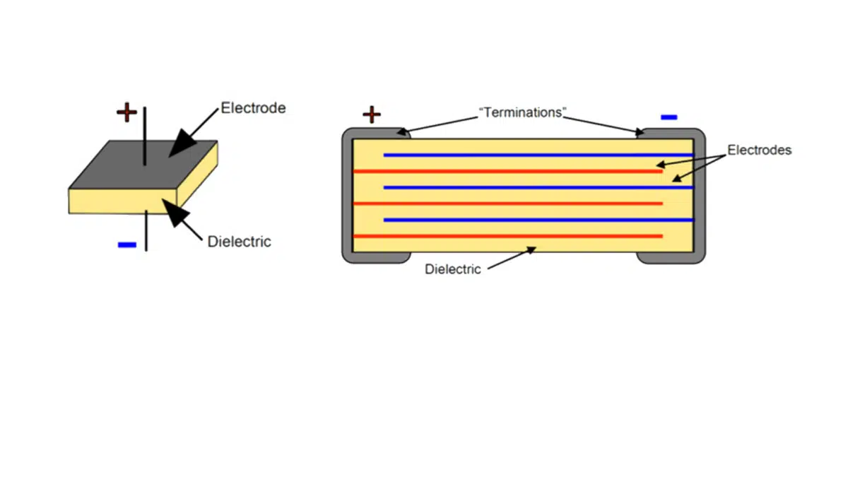
At a high-level, these capacitor types seem similar as both SLCs and MLCCs can be used for charging and storing, filtering, or bypass functions in a circuit. To determine which one is the best fit for your application, let’s first look at the basic structure of each capacitor type. SLCs are the most basic capacitor type available since these capacitors consist of a single layer of dielectric material, or insulating layer, sandwiched between a positive and a negative electrode.

RelatedPosts

Knowles Releases Inductors for Mission-Critical RF Applications

Learn How Supercapacitors Enhance Power System in Knowles eBook

Role of High-Q Ceramic Filters to Overcome GNSS Jamming

An MLCC uses the basic principle of this capacitor design to build multiple layers in the same capacitor, resulting in a single capacitor that provides a capacitance level that is equivalent to using multiple SLCs connected in parallel. This multi-layer design in slightly thicker (taller) than an SLC but decreases the overall footprint needed for a capacitor to achieve higher capacitance – a critical concern for many RF and microwave applications today as size, weight, and power (SWaP) are driving many design decisions. Featured image illustrates the construction of an SLC versus an MLCC.

When an SLC May Be the Best Fit

SLC’s are specifically designed for use in microwave and RF applications. This is because the inherent self-resonant frequency (SRF), which is the point where the capacitor will exhibit the least amount of impedance, of an SLC is the highest of any discrete lumped constant capacitor. Capacitors with a high SRF have low equivalent series resistance (ESR), which is the internal resistance in the capacitor that appears in series with the capacitance of the device.

This is important because, in general, ESR increases as frequency increases, so using a capacitor that has inherently low ESR is necessary. Additionally, since SLCs are formed monolithically, the number of mechanical parts in the SLC is limited, which also contributes to a lower ESR value.

One potential drawback of SLCs is that since it is just a single layer of material, capacitance is heavily dependent on the dielectric constant of the dielectric used, which limits the capacitance that can be achieved. Therefore, SLCs are mainly ideal for high-frequency, low-capacitance applications.

When an MLCC May Be the Best Fit

In general, MLCC’s can be used in a variety of applications since these capacitors have a much higher capacitance range than that of SLCs. This is possible because MLCCs are made with multiple layers of dielectric and conductors. In addition to offering higher capacitance, this design means MLCCs can be used for much higher voltage applications, up to 12 kV for some of our designs. However, since multiple layers of electrodes and dielectric are used, the ESR of an MLCC is usually much higher than that of an SLC. As a result, MLCC’s, even those made with high Q (ultra-low loss) Class 1 dielectrics, can only handle frequencies up to 30 GHz because of the high ESR values relative to SLCs, while SLCs can handle frequencies up to 100 GHz.

When it comes to RF and microwave applications, MLCCs are ideal for applications that require higher capacitance levels and higher operating voltages. However, when looking at applications beyond the RF and microwave industry, MLCCs, especially those taking advantage of a variety of our MLCC innovations, can be used for some of the world’s most demanding applications, including medical implantables, electric vehicles, and high-reliability detonation devices. 

As shown in this post, the uses cases for SLCs and MLCCs are not interchangeable since each capacitor type handles variables such as voltage, frequency, and capacitance differently. In general, SLCs are well-suited for high-frequency, low-voltage RF and microwave applications, while MLCCs can be used for all types of high-capacitance, high-voltage applications within a much more limited frequency range. 

Related

Source: Knowles Precision Devices Blog

Recent Posts

Comparative display of a grain size and domain structure; b free energy; c P-E loops after high-entropy ceramics (HECs) and PGS design. source: Nature Communications  ISSN 2041-1723

Researchers Propose Novel MLCC Dielectric Design to Increase Energy Storage Capacity

24.7.2025
19

Understanding Inductor Dot Markings and Their Application in LTspice

21.7.2025
30

Würth Elektronik Present Efficient Motor Controller Evaluation Kit

8.7.2025
35

Advancements and Applications of Switch Capacitor Power Converters

25.6.2025
44

Accelerating Full Bridge LLC Resonant Converter Design with Frenetic AI

24.6.2025
56

Samsung Delivers Silicon Capacitors to Marwell AI Systems

24.6.2025
98

Smoltek CNF-MIM Capacitor Commercialization Update

11.6.2025
46

Understanding Switched Capacitor Converters

9.6.2025
127

What Track Width To Use When Routing PCB

6.6.2025
51

Capacitance Definition of Non-Linear Voltage Dependent Capacitors

5.6.2025
82

Upcoming Events

Jul 29
16:00 - 17:00 CEST

Impact of Elevated Voltage and Temperature on Molded Power Inductors in DC/DC converters

View Calendar

Popular Posts

  • Buck Converter Design and Calculation

    0 shares
    Share 0 Tweet 0
  • Boost Converter Design and Calculation

    0 shares
    Share 0 Tweet 0
  • Flyback Converter Design and Calculation

    0 shares
    Share 0 Tweet 0
  • LLC Resonant Converter Design and Calculation

    0 shares
    Share 0 Tweet 0
  • What is a Dielectric Constant and DF of Plastic Materials?

    4 shares
    Share 4 Tweet 0
  • Dual Active Bridge (DAB) Topology Explained

    0 shares
    Share 0 Tweet 0
  • Ripple Current and its Effects on the Performance of Capacitors

    3 shares
    Share 3 Tweet 0
  • How to Design an Inductor

    0 shares
    Share 0 Tweet 0
  • MLCC and Ceramic Capacitors

    0 shares
    Share 0 Tweet 0
  • MLCC Case Sizes Standards Explained

    0 shares
    Share 0 Tweet 0

Newsletter Subscription


Passive Components Blog

© EPCI - Leading Passive Components Educational and Information Site

  • Home
  • Privacy Policy
  • EPCI Membership & Advertisement
  • About

No Result
View All Result
  • Home
  • Knowledge Blog
  • Premium Suppliers

© EPCI - Leading Passive Components Educational and Information Site

This website uses cookies. By continuing to use this website you are giving consent to cookies being used. Visit our Privacy and Cookie Policy.
Go to mobile version