


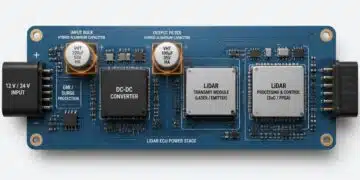


The webinar by Frenetic examines two LLC transformers designed for a 300 W half‑bridge LLC stage with approximately 400 V DC input and 33–56 V output for lithium‑ion battery charging.
Both transformers are sized and optimized using Frenetic’s magnetics design environment, but they target different implementation styles.
Introduction
Designers of isolated DC‑DC converters in the 300 W class increasingly face a choice between conventional wound transformers and planar constructions, especially in compact lithium‑ion battery chargers around 400 V DC input. This article based on Frenetic webinar summarizes a concrete 300 W half‑bridge LLC case study comparing a standard wound transformer against a planar solution, highlighting power density, transformer losses, development effort, and practical integration aspects for engineers and purchasers.
Key Takeaways
- The webinar discusses two LLC converter designs: a standard wound transformer and a planar transformer, both for a 300 W half-bridge LLC stage.
- The ER41 wound transformer balances volume and losses, while the planar ER32 transformer achieves approximately double the power density with a more compact design.
- Planar designs need careful thermal management; forced air or plate cooling is usually necessary, unlike the standard design that can rely on natural convection.
- Both designs perform well, but planar technology becomes favorable when high power density and low profile are needed, especially with existing complex PCBs.
- Choosing between standard and planar magnetics depends on integration potential, prototyping ease, and project requirements.
Standard vs planar 300 W LLC transformers: design trade‑offs and implementation insights
Design brief and operating conditions
The study focuses on a 300 W half‑bridge LLC stage intended for isolated charging of lithium‑ion batteries from a high‑voltage DC bus. The two transformer implementations share the same basic LLC specification so that practical differences arise from the mechanical and magnetic realization rather than from different converter designs.
The converter operates from an input of approximately 400 V DC, producing an output voltage range of 33–56 V DC at a nominal constant power of 300 W. Regulation is achieved by varying the switching frequency roughly between 59 kHz and 122 kHz around a resonant frequency near 60 kHz, with the highest output voltage operating point close to resonance and the lowest output voltage reached at significantly higher frequency. The magnetizing inductance is specified around and the resonant or “stray” inductance around , with a nominal primary‑to‑secondary turns ratio of roughly 3.5–3.6:1. Insulation requirements follow automotive standards with reinforced insulation between primary and secondary, and the natural‑convection design target represents a realistic constraint for many industrial and automotive auxiliary power supplies.
Within this framework, both a standard wound transformer on an ER41 core and a planar transformer on an ER32 core are designed and evaluated in Frenetic’s magnetics environment. The workflow uses the simulator to select the core, estimate flux levels, and quantify losses, while a dedicated planar tool models PCB windings, leakage, capacitances, and frequency‑dependent copper and core losses.
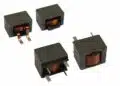
Standard ER41 wound transformer
The conventional solution is based on an ER41 ferrite core in Ferroxcube 3C95, chosen for its balance between volume, available window area, and acceptable height for a 300 W natural‑convection design. The tool’s suggestion is tuned only minimally, reflecting what a typical experienced designer might accept as a first practical iteration.
On the primary side, the transformer uses 18 turns of litz wire with triple insulation to satisfy reinforced insulation requirements and minimize skin and proximity losses in the 60–120 kHz range. The chosen litz construction employs 105 strands of 50 µm diameter, which yields a current density around 13 A/mm² under the worst‑case operating condition, while keeping total primary winding losses close to 1 W. On the secondary side, the winding operates at approximately 30–50 V and therefore does not require additional insulation layers; it uses litz with different strand count and diameter, and two parallel conductors, to handle higher current at low voltage while maintaining reasonable copper losses.
Core‑level analysis at the worst‑case condition (56 V output and 59 kHz) shows an AC flux swing of about 200 mT in 3C95, which remains within typical loss and thermal limits when all relevant operating points are considered. The webinar notes that this low‑frequency, high‑voltage condition turns out to be the worst case for the standard design, even though intuition might suggest that the highest‑current, low‑voltage condition is more critical. This outcome emphasizes the need to assess all realistic operating modes rather than rely on a single “obvious” worst‑case point.
On the thermal side, the ER41 solution is designed for natural convection, with the core and windings sufficiently exposed to airflow. Sample cost for such standard magnetics is relatively modest, on the order of a few to perhaps 5–10 USD per part for small quantities, and in‑house prototyping can be completed in a few hours given access to a magnetics lab. This combination of low barrier to entry, straightforward rework (rewinding or modifying turns), and robust performance makes the ER41 transformer an attractive baseline for many 300 W LLC designs.
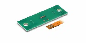
Planar ER32 PCB‑based transformer
To explore higher power density, the planar variant uses an ER32 core from the same family as ER41, again in 3C95 material. While ER32 is one size smaller than ER41, it offers roughly double the achievable power density—about 14 kW per liter for ER41 versus approximately twice that for ER32—because the smaller volume is paired with an optimized flux and winding configuration.
In the planar design, the primary winding is implemented as 28 turns on a multi‑layer PCB, with four turns per layer and one parallel track per turn, using 4 oz copper to limit DC resistance and AC losses at high frequency. The secondary winding is realized as two turns, with two layers per turn and no parallel layers, which simplifies current sharing and soldering considerations. The stack is arranged to remain realistic for manufacturing: the height target is around 4 mm, which can be achieved by sandwiching two standard 2 mm, six‑layer PCBs to obtain a total of 12 copper layers without resorting to exotic PCB technology.
To achieve the desired magnetizing inductance, the ER32 core is gapped symmetrically, with a 0.25 mm gap in each leg. This deliberate gapping controls stored energy and magnetizing current, while the planar tool evaluates fringing field impacts and associated losses. Despite the smaller core, the design maintains an AC flux swing similar to the ER41 solution, around 200 mT under worst‑case conditions, and core losses are actually reduced due to the more compact geometry and higher number of turns.
Unlike the standard transformer, the planar design’s worst‑case point shifts toward a high‑frequency operating condition. The high‑frequency, lower‑voltage point becomes most critical because planar copper loss is more sensitive to frequency and proximity effects, and core loss increases with frequency. This contrast illustrates that planar designs may exhibit different worst‑case regimes than wound designs, reinforcing the need to validate the entire operating envelope.
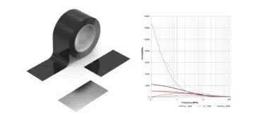
From a thermal perspective, the planar transformer demands more careful management. Air cooling alone is not sufficient at the achieved power density; forced air or, more realistically, plate cooling via a heatsink is required. Efficient heat removal hinges on strong thermal coupling between the PCB and the core, typically implemented by filling gaps with thermally conductive epoxy and using a suitable thermal interface between the core and a metallic baseplate or heatsink. FR‑4 itself is a poor thermal conductor, particularly for embedded copper layers, so thermal paths must be engineered deliberately.
Electrically, the planar layout achieves a primary‑secondary capacitance on the order of 50 pF, which is relatively low for such constructions and favorable for limiting common‑mode currents across the isolation barrier. In contrast, poorly optimized planar designs can reach hundreds of picofarads or more, potentially violating leakage current specifications in mains‑connected applications. The webinar notes that the standard ER41 model does not yet include automatic primary‑secondary capacitance prediction in the tool, while planar capacitance is more readily modeled because of the regular plate‑like geometry.
Quantitative comparison and power density
With both designs calibrated to the same LLC specification, the webinar compares key parameters such as volume, mass, losses, leakage inductance, and interwinding capacitances. While exact numeric details are discussed qualitatively rather than as a detailed table, a few overall conclusions emerge.
Firstly, the ER32 planar transformer roughly halves the volume compared to the ER41 wound part, resulting in about twice the power density for the same 300 W power level. The height reduction is modest—only about 3 mm—but the smaller footprint and reduced core dimensions produce a dramatically more compact component. Secondly, the mass of the planar transformer does not double or otherwise penalize the design despite the increased power density; the two parts remain comparable in weight, which benefits mechanical integration.
More importantly, doubling power density does not double the losses. The planar ER32 solution manages to keep total losses significantly below twice those of the ER41 wound part, due to lower core losses and carefully managed copper geometry. In some operating points the planar losses compare surprisingly well, highlighting that planar technology can achieve both high power density and competitive efficiency when properly optimized.
Leakage inductance is intentionally kept at a similar level in both designs so as not to distort the LLC behavior. In the planar tool, the designer illustrates how modifying layer spacing can increase leakage inductance and reduce capacitance simultaneously, but at the cost of additional copper loss—demonstrating that adjustments to parasitics rarely come for free. The session shows that even substantial increases in leakage (for example, from about 2.9 µH to 9.5 µH) can raise losses appreciably, which reinforces that parasitic tuning must be balanced against efficiency.
Development cost, risk, and iteration
Beyond pure performance, the webinar focuses heavily on development cost and risk, which are especially relevant when deciding whether to adopt planar technology for a given project.
For standard wound transformers, development is relatively forgiving. If a company has an in‑house magnetics lab, prototypes can be built within a couple of hours, using readily available cores and wire. The material cost per prototype is low, often just a few dollars, and any design miscalculations can often be remedied by rewinding or modifying the component. Even outsourcing sample builds to an external manufacturer adds weeks rather than months to the schedule and remains cost‑effective given the small incremental cost per transformer.
By contrast, planar development is dominated by PCB cost. The webinar cites a typical scenario where a small 50 × 50 mm PCB with 6–12 layers of 4 oz copper costs in the range of 500–700 USD for sample quantities, independent of whether one or ten boards are ordered. Copper thickness significantly affects cost: moving from 1–2 oz to 4 oz increases price sharply, yet the higher thickness is necessary for acceptable current handling and losses in this design. Given this high startup cost, engineers are reluctant to “pull the trigger” on multiple exploratory planar designs; the prospective expense of 500–700 USD per iteration makes trial‑and‑error impractical.
Moreover, mistakes in planar designs are far more difficult to remedy. With a 12‑layer board, only errors on the outer layers might be correctable by manual rework; anything deeper effectively requires a new PCB revision. In contrast, a standard wound transformer from a manufacturer can be opened, rewound, or otherwise altered to compensate for minor design missteps, at least in the prototyping phase. Thus, the economic and technical penalty for planar mistakes is much higher.
The webinar also underscores that while LLC converters using standard magnetics are extensively documented in literature and application notes, there is relatively little reference material for designing planar LLC transformers. Without a dedicated tool that includes proximity, fringing field, and capacitive effects, it is extremely difficult to arrive at a robust planar design on the first attempt. Equations alone are not sufficient, especially when fringing fields from the core gaps into the PCB layers can make or break the thermal and loss budget.
Integration strategy and PCB architecture
A central strategic question raised in the discussion is whether the planar transformer should be integrated into the main power PCB or built on a separate board. This decision has major implications for both cost allocation and manufacturability.
In an integrated approach, the main converter PCB already uses a multi‑layer structure with significant copper thickness, and the planar transformer is realized by adding cutouts and transformer‑specific geometry into the same board. In such a case, the high PCB cost is spread across the entire converter, and the transformer is effectively just two core halves plus adhesive. The bill of materials can then treat the transformer as primarily a magnetic cost rather than attributing the entire PCB price to the magnetics alone. This makes planar more economically attractive, especially when the rest of the converter would already demand a complex board.
However, using a 12‑layer, 4 oz board solely to support a simple 300 W converter is rarely justified. For lower‑complexity converters, a more reasonable option is to use a six‑layer main board at 2 mm thickness and a second, structurally similar board dedicated to the transformer region, with the two boards sandwiched together to achieve the required layer count and copper volume. The webinar notes that initial sample cost for such planar boards is largely a fixed startup expense; whether one or ten boards are ordered, the total price does not scale dramatically at these small dimensions, which encourages careful up‑front design.
For purchasers and project managers, the takeaway is that planar magnetics become particularly attractive when the PCB technology roadmap already points toward thick, multi‑layer power boards, or when the incremental cost of adding planar windings to an existing complex PCB is relatively small. If, on the other hand, the transformer PCB is a one‑off high‑layer board solely for the magnetics, the added complexity and cost may outweigh the benefits at 300 W.
Thermal behavior and cooling concepts
Thermal considerations differ markedly between the standard and planar designs, and these differences must be accounted for early in the design‑in phase.
The standard ER41 transformer benefits from direct exposure of windings and core to airflow, and natural convection is adequate at 300 W for the specific losses and flux levels chosen. Forced air can further improve margins, but it is not strictly required in the example. Mounting and thermal interface design are relatively flexible; the transformer can be oriented and secured to take advantage of system‑level airflow, and local hotspots can be addressed through straightforward mechanical changes.
The planar ER32 transformer, in contrast, is much more sensitive to thermal path design. FR‑4’s low thermal conductivity, particularly in the vertical direction, means that embedded copper layers have a limited ability to dissipate heat unless connected via dense thermal vias and copper planes to a heat‑spreading surface. The webinar stresses that core‑to‑PCB thermal coupling is critical: an epoxy or potting compound is typically inserted between the core and the PCB to create a reliable thermal bridge to a heatsink or cold plate. The full stack—from heatsink, through thermal pad, core, potting, PCB, and internal copper—must be considered when estimating steady‑state temperatures.
Because of these complexities, planar designs require either detailed thermal simulation or measurement‑driven iteration; simple current‑density rules of thumb may not capture the real behavior of a multi‑layer planar transformer, especially at high frequencies and with high copper thickness. For larger planar designs, forced air can still play a role, but at 300 W and the given dimensions, plate cooling or direct integration into a cooled baseplate is more realistic.
Parasitics, EMC, and reliability
The webinar addresses parasitic capacitances and leakage inductance as major concerns for resonant converters and highlights their particular importance for planar magnetics.
Planar primary‑secondary capacitance is inherently more predictable than in standard wound transformers because the geometry resembles large parallel plates separated by a known dielectric. This regular structure allows capacitance to be modeled fairly accurately and provides early visibility into expected common‑mode currents across the isolation barrier. However, planar designs can easily overshoot acceptable capacitance values if layers are placed too close or if large overlapping areas are used without sufficient spacing.
In consumer or industrial applications with safety requirements, high primary‑secondary capacitance directly affects leakage current to protective earth. If the capacitance leads to leakage currents above specified limits under AC conditions, the design may fail compliance testing. The webinar suggests that designers must consider both leakage inductance and interwinding capacitance together and compute the first self‑resonant frequency of the transformer; this resonance must remain safely above the operating frequency range and relevant harmonics to avoid undesirable ringing and EMI peaks.
Adjusting planar leakage inductance is more challenging than in wound magnetics. In standard transformers, leakage can be influenced intuitively by changing the relative placement of primary and secondary, adjusting distances, or inserting simple spacers. In the planar case, the relationship between layer spacing, copper geometry, and leakage is more complex, and there is no straightforward analytic recipe for “trimming” leakage to a desired value. The presenter notes that while capacitance can be approximated analytically with good accuracy, leakage inductance generally requires simulation plus measurement.
Despite these difficulties, the planar example demonstrates that acceptable leakage and capacitance values can be achieved with careful design and that parasitic control can be as good or better than in conventional magnetics once the geometry is fully optimized. The repeatable, mechanically constrained structure of planar PCBs also improves consistency between units, which is beneficial for series production and EMC predictability.
Case Study Summary
LLC converter specification
- Topology: Half‑bridge LLC resonant converter.
- Input: Approximately 400 V DC.
- Output: 33–56 V DC, targeting lithium‑ion battery packs.
- Power: 300 W across the full output voltage range.
- Frequency:
- Resonant frequency around 60 kHz.
- Operating frequency range roughly 59–122 kHz to regulate the output.
- Inductances:
- Magnetizing inductance Lm around 270 µH.
- Series or “stray” inductance Lr around 60 µH, as derived from the mechanical and winding arrangement.
- Turns ratio:
- Around 3.5–3.6:1 from primary to secondary, consistent with 400 V input and 33–56 V output window.
- Insulation:
- Reinforced insulation according to automotive requirements, with adequate creepage and clearance gaps.
Standard transformer details
- Core: ER41 ferrite from Ferroxcube, material 3C95.
- AC flux:
- AC flux swing in the core around 200 mT at the worst‑case operating condition, with other operating points at lower flux.
- Design checks confirm that BAC remains in a safe region for losses and thermal limits over the full operating set.
- Winding layout:
- Interleaved primary‑secondary‑primary structure to balance leakage and coupling.
- Primary litz wire chosen to control skin and proximity losses at 60–120 kHz.
- Secondary litz with adjusted strand count and diameter to handle high current at low voltage without excess copper loss.
- Thermal:
- Designed for free (natural) convection using the chosen ER41 volume.
- Winding and core temperatures remain within typical design limits for magnetics in this power range.
Planar transformer details
- Core: ER32 ferrite from the same family as ER41, also 3C95.
- Power density and volume:
- Approximate doubling of power density relative to the ER41 solution.
- Overall volume around half that of the standard transformer, with modest height reduction and a significantly smaller footprint.
- PCB stackup:
- Target total PCB height around 4 mm, achievable by stacking two standard 2 mm, six‑layer PCBs.
- This allows use of standard fabrication technologies while achieving 12 total copper layers.
- Winding configuration:
- Primary: 28 turns total, 4 turns per layer over multiple layers, 4 oz copper to keep DC resistance and AC losses under control.
- Secondary: 2 turns realized with 2 layers per turn, also in 4 oz copper, without parallel layers to simplify current sharing and assembly.
- Gap and inductance:
- Symmetric 0.25 mm gaps in each leg of the ER32 core to set Lm and ensure predictable magnetizing current.
- Thermal management:
- Forced air or plate cooling is required; natural convection is not sufficient at this power density.
- Effective heat removal requires good thermal coupling between PCB and core, typically achieved by filling the gap region with thermally conductive epoxy or potting compound and mounting the assembly on a heatsink.
- Parasitics:
- Primary‑secondary capacitance in the tens of picofarads range, much better than naive planar layouts that can reach hundreds of picofarads or more.
- Leakage inductance and capacitance jointly determine the first self‑resonant frequency, which must remain comfortably above the converter operating band.
Quantitative comparison (conceptual)
| Parameter | Standard ER41 wound | Planar ER32 PCB‑based |
|---|---|---|
| Core family | ER41, 3C95 | ER32, 3C95 |
| Power rating | 300 W | 300 W |
| Cooling | Natural convection | Forced air or plate cooling |
| Volume | Baseline | ≈ 0.5 × standard volume |
| Height | Higher | ≈ 3 mm lower |
| Power density | Baseline | ≈ 2 × standard |
| Total losses (min–max) | Low, within expectations | Higher but < 2 ×, still efficient |
| Primary‑secondary capacitance | Not yet modeled in tool | ≈ 50 pF |
| Sample cost (low volume) | Few USD per piece | PCB cost ≈ 500–700 USD for small 50 × 50 mm panel at 4 oz, 6–12 layers |
| Rework / iteration effort | Easy to re‑wind, low risk | PCB respin required, high NRE |
The key qualitative observation is that doubling power density does not require doubling losses in this case. With careful planar layout and flux management, the smaller core actually runs with lower core loss, and winding losses stay manageable, so total losses scale favorably compared to volume.
Practical selection guidelines
From a performance standpoint, standard wound magnetics on ER41 perform very well, achieving low losses, acceptable temperature rise under natural convection, and robust insulation margins. For projects where volume and height constraints are moderate, and where rapid, low‑cost prototyping is valuable, conventional magnetics remain an excellent default choice.
Planar magnetics on ER32 become compelling when system‑level constraints demand high power density and low profile, or when further efficiency improvements beyond what can be realistically achieved with smaller wound cores are required. The presenter notes that attempts to implement a 300 W LLC transformer using the smaller planar core in a conventional wound fashion led to losses on the order of 10–11 W—far higher than the couple of watts seen in the optimized planar and ER41 designs—indicating that planar technology is effectively the only realistic way to push power density and efficiency further within the available volume.
Economically, planar makes most sense when the transformer can be integrated into an existing complex PCB or when project volumes justify the high initial PCB NRE. Without an adequate modeling tool—such as the planar‑aware simulator demonstrated—moving to planar is risky and expensive due to the high cost of design errors. In contrast, standard magnetics are more forgiving, both in terms of design iteration and manufacturing rework.
The session also emphasizes that the worst‑case operating point and parasitic behavior are not necessarily intuitive. Engineers should therefore treat planar and standard designs as distinct optimization problems, avoid relying solely on previous experience with wound magnetics, and leverage dedicated simulation tools or measurement campaigns to validate thermal, magnetic, and EMC performance before committing to production.
When to choose which
From the presented 300 W case, a practical rule emerges:
- If you can integrate the planar transformer into an existing multi‑layer power PCB (and you have proper modeling tools), planar will give you a significant power density advantage and potentially better efficiency at the same or only slightly higher loss.
- If you cannot integrate, and you would need a dedicated, high‑layer‑count, thick‑copper PCB only for the transformer, the initial cost and risk may outweigh the benefits at 300 W.
- Standard wound magnetics remain a strong baseline: they perform very well in this design, are easy to prototype, and are more forgiving to rework.
- For still higher efficiency and power density beyond what ER41 can deliver with acceptable losses, planar becomes the only realistic path; attempts to use smaller standard cores in this power range can lead to excessive losses.
Source
This article summarizes and interprets the content of a Frenetic webinar titled “Two LLC 300W designs, 1 standard VS 1 planar — which one wins?”, in which the presenter walks through the design of two 300 W LLC transformers using Frenetic’s magnetics design tools and discusses standard versus planar approaches from a practical engineering perspective.
References
- Frenetic webinar: Two LLC 300W designs, 1 standard VS 1 planar — which one wins?
- Frenetic – company LinkedIn page
FAQ
The wound transformer (ER41) offers a straightforward and low‑risk development path. Engineers can prototype it in‑house within a few hours if a magnetics lab is available, and sample costs are typically only a few dollars per piece. The design uses 18 primary turns of triple‑insulated litz wire and an interleaved primary–secondary–primary arrangement, achieving around 200 mT AC flux swing with approximately 1 W of primary winding losses at the worst‑case operating point. Natural convection cooling is sufficient at 300 W, and any mistakes in turns or topology can usually be corrected by rewinding or minor rework, which makes this approach attractive for designs with moderate power‑density requirements.
The planar transformer (ER32) roughly halves the magnetic volume compared with the ER41 solution and therefore doubles the power density for the same 300 W output. It uses 28 primary turns and 2 secondary turns implemented on a multi‑layer PCB, with around 4 oz copper and a 0.25 mm gap in each core leg to set the magnetizing inductance. Despite the smaller core, total losses are kept well below twice those of the standard part, and core losses can even be lower due to the optimized turns count and geometry. Planar windings also provide highly repeatable parasitics and a relatively low primary‑secondary capacitance on the order of tens of picofarads, which is helpful for EMC and leakage current control.
In the planar case, the dominant cost driver is the PCB, not the ferrite core. A small 50 × 50 mm PCB with 6–12 layers of 4 oz copper can cost on the order of several hundred dollars just for prototypes, largely independent of whether one or ten boards are ordered. If the design contains errors, most issues cannot be fixed by rework because the transformer uses multiple internal layers; a new PCB spin is required. In contrast, a standard ER41 transformer prototype costs only a few dollars in materials, and many mistakes can be corrected by rewinding or modifying the component. This means that without a dedicated planar design tool that can model proximity, fringing, and capacitances, trial‑and‑error planar iterations are economically unattractive.
The ER41 wound transformer is designed for natural convection and benefits from relatively direct airflow around the core and windings. Its losses and flux levels are chosen so that temperatures remain within safe limits without special cooling hardware. The ER32 planar transformer, however, operates at much higher power density and cannot rely on air cooling alone. Effective heat removal requires plate cooling or heatsink mounting, plus a well‑designed thermal path from the PCB copper through thermally conductive epoxy and the ferrite core into a baseplate. Because FR‑4 has low thermal conductivity, especially for embedded layers, planar designs depend heavily on thermal simulation or measurement to confirm that the internal copper and core remain within their allowable temperature range.
Planar transformers are most attractive when system‑level requirements demand very high power density, low profile, or tight mechanical integration with an existing multi‑layer power PCB. If the main converter board already uses thick copper and multiple layers, integrating the planar transformer into that board allows the PCB cost to be shared across the entire design, making the transformer itself effectively just two core halves plus adhesive. In such cases, planar can deliver higher power density and competitive efficiency at an acceptable total cost. If, however, the transformer would require a dedicated 12‑layer, 4 oz PCB solely for the magnetics, and the project lacks appropriate modeling tools, a well‑designed standard ER41 transformer often remains the more economical and lower‑risk choice at 300 W.
How to choose between standard and planar transformers for a 300 W LLC converter
- Step 1: Define electrical and safety requirements
Start by fixing the LLC specification: input voltage around 400 V DC, output range of approximately 33–56 V DC, and a constant 300 W power target. Determine the required switching‑frequency range, typically around 59–122 kHz, and define magnetizing and resonant inductances (for example ). At the same time, establish insulation requirements such as reinforced isolation for automotive or industrial use, including creepage and clearance constraints, because these parameters will strongly influence core choice and winding geometry.
- Step 2: Establish mechanical and thermal constraints
Assess the available volume and height in the target application, as well as the cooling concept. If you can accommodate an ER41‑class core with natural convection and moderate height, a standard wound transformer is immediately viable. If enclosure height and footprint are severely constrained, or if the design already uses a cooled baseplate, you may lean toward a more compact ER32 planar transformer. In parallel, decide whether your system can provide forced air or plate cooling, since planar technology at this power density typically cannot rely on natural convection alone.
- Step 3: Evaluate prototyping budget and available tools
Compare the development cost and risk for both options. For the standard ER41 solution, factor in that prototypes can be built quickly in‑house with low material cost and that design mistakes are often fixable by rewinding. For the planar ER32 option, budget several hundred dollars for each multi‑layer, thick‑copper PCB spin and recognize that most design errors will require a new board revision. Confirm whether you have access to a planar‑aware magnetics tool that models proximity, fringing, and interwinding capacitance; if not, achieving a robust planar design on the first attempt is unlikely and the financial risk increases.
- Step 4: Analyze losses, flux density, and worst‑case operating points
Use a magnetics design or simulation tool to create both an ER41 wound transformer and an ER32 planar transformer under the same LLC specification. For each design, verify that the AC flux swing in the chosen ferrite material stays within safe limits across all operating points and identify which combination of output voltage and frequency leads to the worst‑case loss scenario. Expect that the wound transformer may be most stressed at a low‑frequency, high‑voltage point, while the planar transformer may reach its worst case at higher frequency due to stronger frequency‑dependent copper and core losses. Compare total losses and temperature rise for both options against your thermal constraints.
- Step 5: Consider parasitics, EMC, and integration options
Inspect leakage inductance and primary‑secondary capacitance for each design and ensure that the resulting self‑resonant frequency remains comfortably above the converter’s operating band. For the planar transformer, confirm that the modeled primary‑secondary capacitance does not drive leakage currents beyond your regulatory limits, and adjust layer spacing or overlap as needed while monitoring loss penalties. Finally, decide whether the planar transformer can be integrated into the main converter PCB or implemented as a separate board; if integration is feasible, the incremental PCB cost may be acceptable, whereas a dedicated high‑layer transformer board may not be economical at 300 W.