
Passive Components Blog
No Result
View All Result
  • Home
  • News
    • All
    • Aerospace & Defence
    • Antenna
    • Applications
    • Automotive
    • Capacitors
    • Circuit Protection Devices
    • electro-mechanical news
    • Filters
    • Fuses
    • Inductors
    • Industrial
    • Integrated Passives
    • inter-connect news
    • Market & Supply Chain
    • Market Insights
    • Medical
    • Modelling and Simulation
    • New Materials & Supply
    • New Technologies
    • Non-linear Passives
    • Optoelectronics and Isolation
    • Oscillators
    • Passive Sensors News
    • Resistors
    • RF & Microwave
    • Telecommunication
    • Weekly Digest
    Samtec automotive interconnect technologies for software-defined vehicle electronics

    Samtec Links Automotive Connector Demands to Software-Defined Cars

    Panasonic Industry PGS graphite heat-spreading technology and passive components for spacecraft thermal management

    Panasonic Targets Space Thermal Design at SPCD 2026

    tungsten-bronze-ceramic-capacitor-stack

    Tungsten bronze capacitors combine high κ and thermal stability

    Bourns MF-ASMF Series surface-mount PPTC resettable fuses in the manufacturer product photograph

    Bourns Announces 0402 PPTC Fuses Target Low-Current Protection

    Conceptual illustration of Littelfuse AQ4315-01ETG and SP4315-01WTG TVS diode applications on high-speed PCB data lines

    Littelfuse Adds Low-Capacitance TVS Diodes for Fast Data Links

    Datasheet-style illustration of a TDK MLJ1608-G multilayer chip inductor with end terminals

    TDK Expands1608 Inductors for Automotive PoC Filters

    Murata electronica 2026 technology preview featuring MGJ2T2 power converters and SCI36LT inertial sensors.

    Murata Previews SiC Power and AI Sensors at electronica 2026

    Ruggedized passive component customization overview covering capacitors, resistors and inductors.

    Ruggedized Passive Components: Reliability Beyond the Datasheet

    YAGEO Group AS Series resin-coat-less multilayer piezoelectric actuator with lead wires for high-speed industrial motion control

    YAGEO Unveils Multilayer Piezoelectric Actuators

    Trending Tags

    • Ripple Current
    • RF
    • Leakage Current
    • Tantalum vs Ceramic
    • Snubber
    • Low ESR
    • Feedthrough
    • Derating
    • Dielectric Constant
    • New Products
    • Market Reports
  • Knowledge Blog
  • Dossiers
    • AI Hardware Dossier
    • Automotive Dossier
    • Industrial Robotics Dossier
    • Power Converter Dossier
    • Capacitor Dossier
    • Resistor Dossier
    • Inductor Dossier
    • Circuit Protection Dossier
  • Suppliers
    • Who is Who
  • PCNS
    • PCNS 2025
    • PCNS 2023
    • PCNS 2021
    • PCNS 2019
    • PCNS 2017
  • Events
  • Home
  • News
    • All
    • Aerospace & Defence
    • Antenna
    • Applications
    • Automotive
    • Capacitors
    • Circuit Protection Devices
    • electro-mechanical news
    • Filters
    • Fuses
    • Inductors
    • Industrial
    • Integrated Passives
    • inter-connect news
    • Market & Supply Chain
    • Market Insights
    • Medical
    • Modelling and Simulation
    • New Materials & Supply
    • New Technologies
    • Non-linear Passives
    • Optoelectronics and Isolation
    • Oscillators
    • Passive Sensors News
    • Resistors
    • RF & Microwave
    • Telecommunication
    • Weekly Digest
    Samtec automotive interconnect technologies for software-defined vehicle electronics

    Samtec Links Automotive Connector Demands to Software-Defined Cars

    Panasonic Industry PGS graphite heat-spreading technology and passive components for spacecraft thermal management

    Panasonic Targets Space Thermal Design at SPCD 2026

    tungsten-bronze-ceramic-capacitor-stack

    Tungsten bronze capacitors combine high κ and thermal stability

    Bourns MF-ASMF Series surface-mount PPTC resettable fuses in the manufacturer product photograph

    Bourns Announces 0402 PPTC Fuses Target Low-Current Protection

    Conceptual illustration of Littelfuse AQ4315-01ETG and SP4315-01WTG TVS diode applications on high-speed PCB data lines

    Littelfuse Adds Low-Capacitance TVS Diodes for Fast Data Links

    Datasheet-style illustration of a TDK MLJ1608-G multilayer chip inductor with end terminals

    TDK Expands1608 Inductors for Automotive PoC Filters

    Murata electronica 2026 technology preview featuring MGJ2T2 power converters and SCI36LT inertial sensors.

    Murata Previews SiC Power and AI Sensors at electronica 2026

    Ruggedized passive component customization overview covering capacitors, resistors and inductors.

    Ruggedized Passive Components: Reliability Beyond the Datasheet

    YAGEO Group AS Series resin-coat-less multilayer piezoelectric actuator with lead wires for high-speed industrial motion control

    YAGEO Unveils Multilayer Piezoelectric Actuators

    Trending Tags

    • Ripple Current
    • RF
    • Leakage Current
    • Tantalum vs Ceramic
    • Snubber
    • Low ESR
    • Feedthrough
    • Derating
    • Dielectric Constant
    • New Products
    • Market Reports
  • Knowledge Blog
  • Dossiers
    • AI Hardware Dossier
    • Automotive Dossier
    • Industrial Robotics Dossier
    • Power Converter Dossier
    • Capacitor Dossier
    • Resistor Dossier
    • Inductor Dossier
    • Circuit Protection Dossier
  • Suppliers
    • Who is Who
  • PCNS
    • PCNS 2025
    • PCNS 2023
    • PCNS 2021
    • PCNS 2019
    • PCNS 2017
  • Events
No Result
View All Result
Passive Components Blog
No Result
View All Result

Why Power Inductors Use a Ferrite Core With an Air Gap

20.4.2026
Reading Time: 16 mins read
A A

This post is based on edited tutorial video by Sam Ben-Yaakov that provides an educational content about power inductor design fundamentals and explains why power inductors use a ferrite cores with a gap.

Power inductors built around a gapped ferrite core are one of the most common building blocks in switch‑mode power supplies, PFC stages, DC‑DC converters and filter chokes. This article explains, from first principles, why designers choose ferrite, why a gap is introduced, and how the gap length is determined — based on a tutorial by Prof. Sam Ben‑Yaakov.

RelatedPosts

TLVR Coupled Inductors: Fast Load-Step Response and Current-Dependent Ballast-Inductor Optimisation

B–H Curve-Based Inductor Modelling in LTspice: A Current-Dependent Magnetic Model

Current-Dependent Inductors: Using Non-Linear Inductance in Buck Converters and PFC Stages

Key Takeaways

  • Power inductors use a ferrite core with a gap to achieve smaller size and prevent saturation.
  • Ferrite provides high permeability, while the air gap allows designers to manage inductance and control AC flux swings.
  • Designers must size the gap to meet saturation and core loss requirements effectively.
  • Both low-permeability powder cores and ferrite cores with gaps offer unique advantages for different frequency ranges.
  • Understanding the interaction of core properties helps engineers choose the right inductor type based on application needs.

Why a ferrite core in the first place

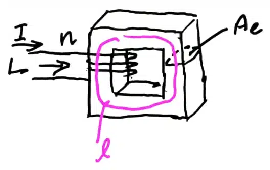
The starting point is the basic definition of inductance:

L=NΦIL = \frac{N \Phi}{I}Combining this with Φ=B⋅A\Phi = B \cdot A, B=μ0μrHB = \mu_0 \mu_r H and Ampère’s law H=NIℓH = \frac{N I}{\ell} gives the classical expression:

L=N2μ0μrAℓL = \frac{N^2 \mu_0 \mu_r A}{\ell}The inductance is linearly proportional to the relative permeability μr\mu_r. A ferrite such as Ferroxcube 3C98 offers a relative permeability on the order of 2000–4000, versus 1 for air. For a given target inductance, higher μr\mu_r allows a smaller cross‑section AA or fewer turns NN.

In practice this means one thing: the main purpose of the ferrite is to shrink the physical size of the inductor.

Saturation and core losses

High permeability comes with two hard limits on the magnetic flux density BB:

  • Saturation. Ferrite materials saturate roughly between 300 and 400 mT. Above that level the B–H slope collapses, permeability drops and the inductor stops behaving as an inductor.
  • Core losses. AC swings of BB dissipate energy. Loss per unit volume grows strongly with the peak AC flux density B^\hat{B} and with frequency.

Starting again from Ampère’s law and B=μ0μrHB = \mu_0 \mu_r H

Bmax=μ0μrNImaxℓB_{max} = \mu_0 \mu_r \frac{N I_{max}}{\ell}This expression reveals the tension in the design: high μr\mu_r is desirable for size, but it directly drives BmaxB_{max} upward for a given current. When current — and therefore stored energy 12LI2\tfrac{1}{2} L I^2 — is high, a lower effective permeability is required to keep BmaxB_{max}​ within safe limits.

Option 1: low‑permeability powder cores

One way to reduce effective permeability is to use powder or distributed‑gap materials such as Kool Mµ from Magnetics, available with relative permeabilities as low as 20–50. These materials are produced by mixing ferromagnetic particles with an inert binder, creating a distributed air gap throughout the volume.

The limitation is frequency. Powder cores typically perform well up to around 50–100 kHz. At a few hundred kHz, and certainly at 1 MHz, their losses become prohibitive when the ripple component of B is significant. For high‑frequency converters another solution is needed.

Option 2: a ferrite core with a discrete air gap
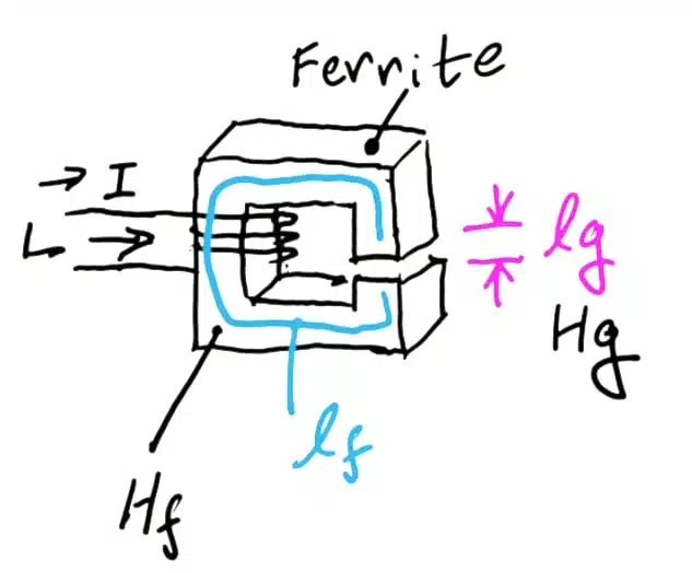
This is the classical topology of modern SMPS inductors. Applying Ampère’s law along a path that crosses both the ferrite and the gap:

NI=HFℓF+HGℓGN I = H_F \ell_F + H_G \ell_GSubstituting H=B/μH = B / \mu for each region and solving for B:

B=NIℓFμ0μr+ℓGμ0B = \frac{N I}{\dfrac{\ell_F}{\mu_0 \mu_r} + \dfrac{\ell_G}{\mu_0}}Because μr\mu_r​ is large, the first term in the denominator is usually much smaller than the second, even though the ferrite path is geometrically much longer than the gap. A useful approximation is therefore:

B≈μ0NIℓGB \approx \frac{\mu_0 N I}{\ell_G}The gap length directly sets the peak flux density: the longer the gap, the lower BBB, and the further the core is kept from saturation and from excessive AC losses.

Effective permeability of a gapped core

Plugging the approximation above into L=NΦ/IL = N \Phi / I and rearranging against the total magnetic path length yields an expression that mirrors the ungapped case, but with an effective permeability:

μeff≈ℓFℓG\mu_{eff} \approx \frac{\ell_F}{\ell_G}A core with a 100 mm magnetic path length and a 1 mm gap therefore behaves as if it had a relative permeability of around 100. By selecting the gap, the designer effectively dials in the permeability needed for the application, decoupling it from the raw material property of the ferrite.

Rod inductors follow the same rules

Rod‑core inductors, with their open magnetic structure, can be viewed as an extreme case of a very large air gap. The flux spreads outside the rod, so the closed‑form equations above no longer apply cleanly, but the physical argument is identical: the ferrite rod raises effective permeability above free air, reducing the required turns count or cross‑section, while the open return path prevents saturation at high currents.

Design‑in notes for engineers

  • Choose ferrite when switching frequencies are high (hundreds of kHz to MHz) and core losses dominate the thermal budget.
  • Choose powder / distributed‑gap cores such as Kool Mµ for lower‑frequency, high‑ripple or PFC chokes where gradual saturation and mechanical simplicity are advantageous.
  • Size the gap for two independent constraints: keep BpeakB_{peak} below saturation at ImaxI_{max}, and keep B^ac\hat{B}_{ac}​ low enough that volumetric core losses remain within the allowable temperature rise.
  • Remember the trade‑off: widening the gap lowers B and inductance, so more turns (and therefore more copper loss and winding space) are required to restore the target L.
  • Fringing flux around the gap increases winding losses; keep windings away from the gap region or use distributed gaps for high‑frequency designs.

Exact material data (saturation BsatB_{sat}​, loss curves, temperature dependence) should always be taken from the manufacturer datasheet for the specific ferrite grade or powder mix being considered.

Conclusion

A ferrite core with a discrete air gap is not a compromise — it is a deliberate way to combine two desirable properties in a single magnetic component. The ferrite provides the high permeability needed to keep the inductor compact and efficient at high switching frequencies, while the gap sets an effective, lower permeability that prevents saturation and controls AC flux swings.

In practice, the gap length becomes the main design knob: it defines Bpeak, the effective permeability μeff≈ℓF/ℓG​, and indirectly the number of turns required to reach the target inductance. Understanding this interaction allows power‑electronics engineers to choose between gapped ferrite, distributed‑gap powder cores such as Kool Mµ, or open rod structures based on frequency, ripple and energy‑storage requirements rather than on rules of thumb.

FAQ

Why is a ferrite core used in power inductors?

Ferrite offers a high relative permeability (typically 2000–4000), which dramatically increases inductance for a given number of turns and cross‑section. This allows designers to build physically smaller inductors for the same inductance value, which is critical in modern switch‑mode power supplies.

Why is an air gap added to a ferrite core?

Without a gap, a high‑permeability ferrite saturates at relatively low currents because the flux density B is directly proportional to permeability. Introducing a small air gap reduces the effective permeability and therefore the peak B, keeping the core safely below its saturation limit (around 300–400 mT for typical ferrites) and limiting AC core losses.

How does the gap length affect inductance and saturation?

A longer gap lowers both the peak flux density and the inductance. As a rule of thumb, the effective permeability of a gapped core is approximately the ratio of the ferrite path length to the gap length, so doubling the gap roughly halves the effective permeability and the inductance per turn squared.

When should powder cores like Kool Mµ be used instead of gapped ferrite?

Powder cores with a distributed air gap, such as Magnetics Kool Mµ, are well suited to lower switching frequencies (typically up to 50–100 kHz) and applications with high DC bias and soft saturation characteristics, such as PFC chokes. For higher frequencies in the hundreds of kHz to MHz range, gapped ferrite usually offers significantly lower losses.

Do rod‑core inductors follow the same principles?

Yes, conceptually. A rod inductor can be viewed as a ferrite core with a very large open air gap. The rod still raises the effective permeability above free air, reducing the required turns, while the open flux return path prevents hard saturation — at the cost of higher external stray field and EMI considerations.

What causes core losses in gapped ferrite inductors?

Core losses are driven mainly by the peak AC flux density and the switching frequency. Hysteresis and eddy‑current losses grow strongly with both, so the gap must be sized not only to avoid DC saturation but also to keep the AC component of B low enough to respect the allowable temperature rise of the core material.

Source

This article is based on the tutorial “Power Electronics Fundamentals: Why ferrite and a gap in power inductors?” by Prof. Sam Ben‑Yaakov, published on his YouTube channel. Material references (Ferroxcube 3C98 ferrite and Magnetics Kool Mµ powder cores) are mentioned as given in the original presentation.

References

  1. Sam Ben‑Yaakov – Power Electronics Fundamentals: Why ferrite and a gap in power inductors? (YouTube)
  2. Ferroxcube 3C98 ferrite material overview
  3. Magnetics Kool Mµ powder core family

Related

Source: Sam Ben-Yaakov

Recent Posts

Panasonic Industry PGS graphite heat-spreading technology and passive components for spacecraft thermal management

Panasonic Targets Space Thermal Design at SPCD 2026

8.10.2026
3
Datasheet-style illustration of a TDK MLJ1608-G multilayer chip inductor with end terminals

TDK Expands1608 Inductors for Automotive PoC Filters

6.10.2026
7
Ruggedized passive component customization overview covering capacitors, resistors and inductors.

Ruggedized Passive Components: Reliability Beyond the Datasheet

6.10.2026
21
YAGEO Group PMT6709NLT and PHT7249NLT GDSC SMD LLC gate-drive transformers for SiC and GaN switching applications

YAGEO Introduces LLC Transformers for SiC and GaN Gate Drives

2.10.2026
25
Würth Elektronik electronica 2026 presentation featuring electronic components, PCB technologies and high-current PowerBusbar connection solutions.

Würth Elektronik Previews Components, PCBs and Power Solutions at electronica 2026

30.9.2026
27
Bourns SRP201210V low-profile shielded SMD power inductors for compact portable electronics

Bourns Releases Compact Shielded Power Inductors

30.9.2026
22
TDK and TAIYO YUDEN business alliance announcement for advanced MLCCs and inductors supporting AI infrastructure.

TDK and TAIYO YUDEN Explore Alliance for MLCCs and Inductors

29.9.2026
136
Coilcraft CSX7045 surface-mount current sense transformers with compact chip-style package

Coilcraft Extends Current Sense Transformers with 1.8 kVrms Isolation

29.9.2026
14
TLVR multiphase coupled inductors, auxiliary ballast inductor

TLVR Coupled Inductors: Fast Load-Step Response and Current-Dependent Ballast-Inductor Optimisation

24.9.2026
65

Upcoming Events

Oct 9
18:00 - 19:00 CEST

Edgewater Research 3Q26 Electronic Components Review Outlook Webinar

Oct 14
17:00 - 18:00 CEST

Live Demo! Discover KYOCERA AVX Antenna Integrator Studio (AIS)

Oct 19
15:00 - 16:00 CEST

ESCC-qualified Pt Temperature Sensors for Space Applications

View Calendar

Popular Posts

  • Buck Converter Design and Calculation

    0 shares
    Share 0 Tweet 0
  • Boost Converter Design and Calculation

    0 shares
    Share 0 Tweet 0
  • LLC Resonant Converter Design and Calculation

    0 shares
    Share 0 Tweet 0
  • Flyback Converter Design and Calculation

    0 shares
    Share 0 Tweet 0
  • Capacitor Charging and Discharging

    0 shares
    Share 0 Tweet 0
  • Resistor Symbols

    0 shares
    Share 0 Tweet 0
  • Audio Capacitors: Choosing Capacitors for Crossover Circuits

    0 shares
    Share 0 Tweet 0
  • Thermistors Basics, NTC and PTC Thermistors

    0 shares
    Share 0 Tweet 0
  • MLCC and Ceramic Capacitors

    0 shares
    Share 0 Tweet 0
  • RF Connector Types: How To Choose the Right One

    0 shares
    Share 0 Tweet 0

Newsletter Subscription


Passive Components Blog

© 2015–2026
All rights reserved

  • Home
  • Privacy Policy
  • EPCI Membership & Advertisement
  • About

No Result
View All Result
  • Home
  • Knowledge Blog
  • Dossiers
  • PCNS

© 2015–2026
All rights reserved